-
Notifications
You must be signed in to change notification settings - Fork 1
AD8367: RMS amp board modification
NOTE: The process outlined in this page was intended to be informational with regard to capturing "Laserdisc" RF. If you are intending to only capture VHS RF, you don't need to do this.
It goes without saying, but i'm going to say it anyway, you should double check each connection after each mod, with your multimeter. It can save you trouble later... (yes, i'm going to say this on almost every mod page!)
The amp boards sold on ebay and aliexpress are most assuredly not configured for optimal use at the frequencies we want, so some modifications are required. The AD8367 has internal 200 ohm termination, which works well with the laserdisc players i have tested. To prevent and DC issues, we install a capacitor on the input and output signal path.
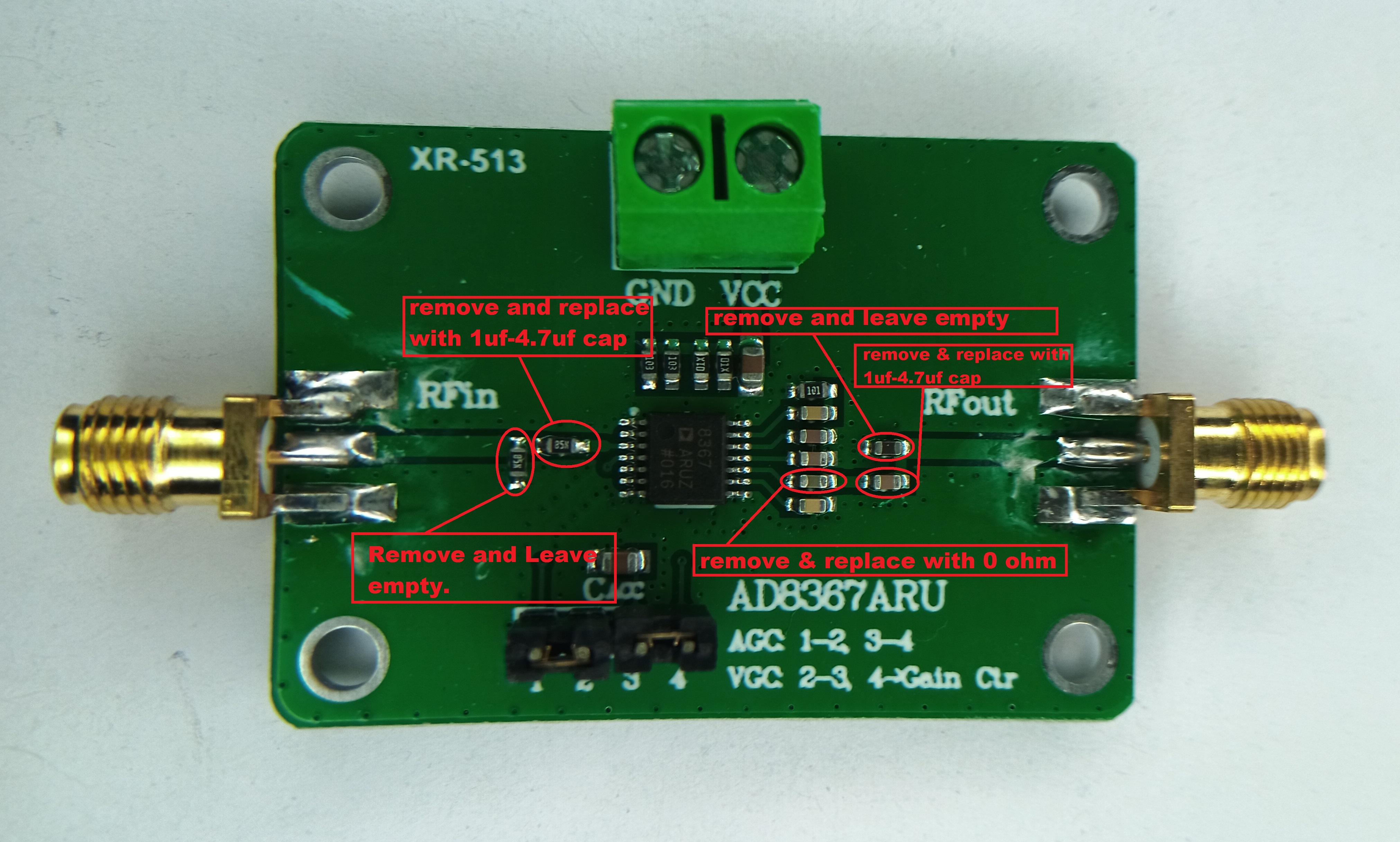
Unfortunately, the AD8367 RMS boards i have, have no indicators naming the components. So i marked up the image directly. Remove the black jumpers that configure RMS mode for now (but make sure to put them back later!). ADDITIONALLY the boards seem to be quite fragile, the traces come up off the PCB easily. Take extra caution to be gentle.
Here's a pre modification picture of the RMS board, for reference:https://github.com/tandersn/cxadc-hw-mod/blob/main/X_Pictures/ad8367_RMS/stockAD8367_RMS%20.jpg?raw=true
- Proceed to modify the amp board as notated in this picture:

- Optional, but recommended, remove the power supply block (green in this picture) and solder the wires from the battery pack directly to it. I have found it to be problematic and have intermittent connectivity issues.
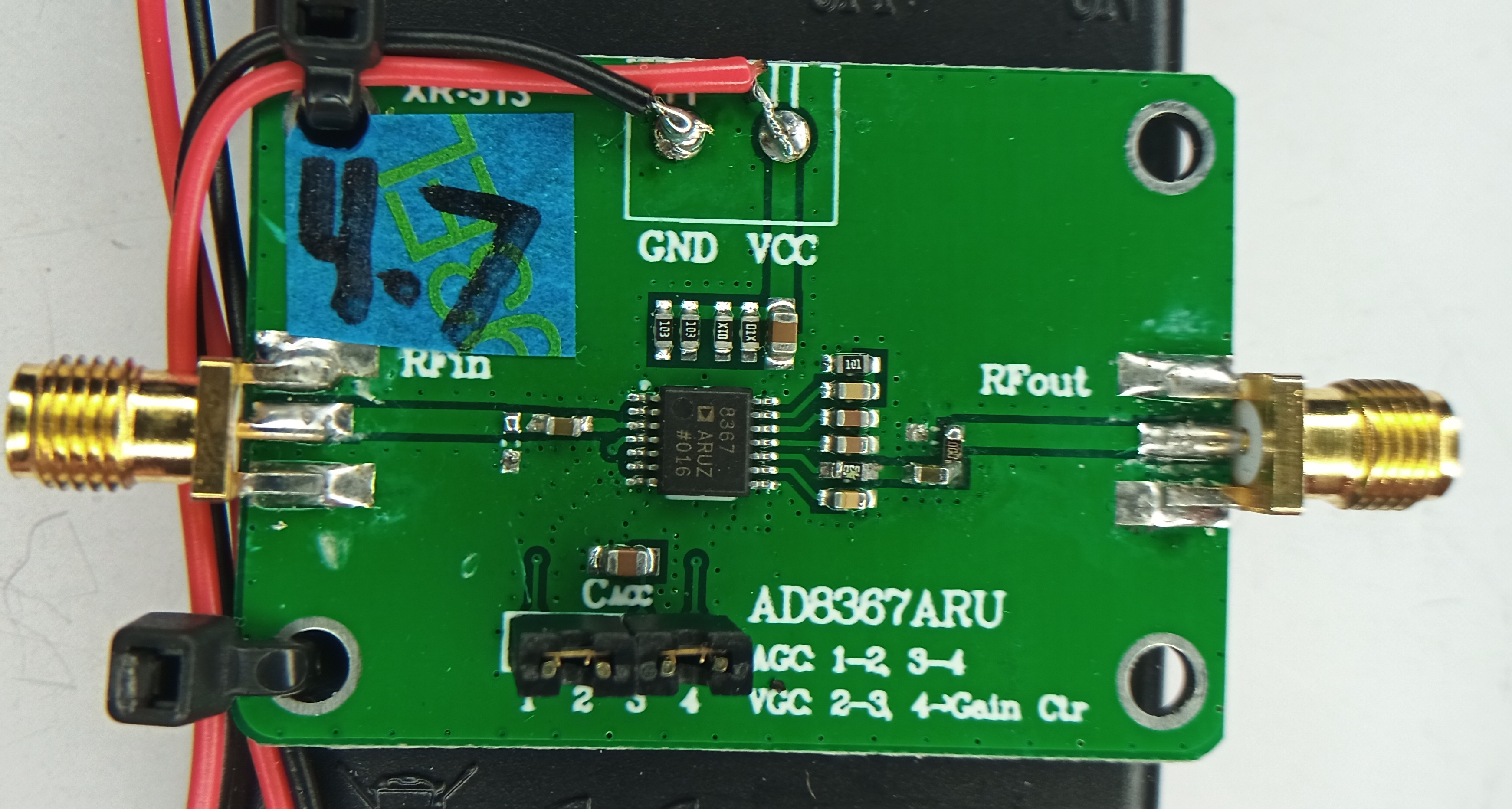
- After mods you should have something like this:

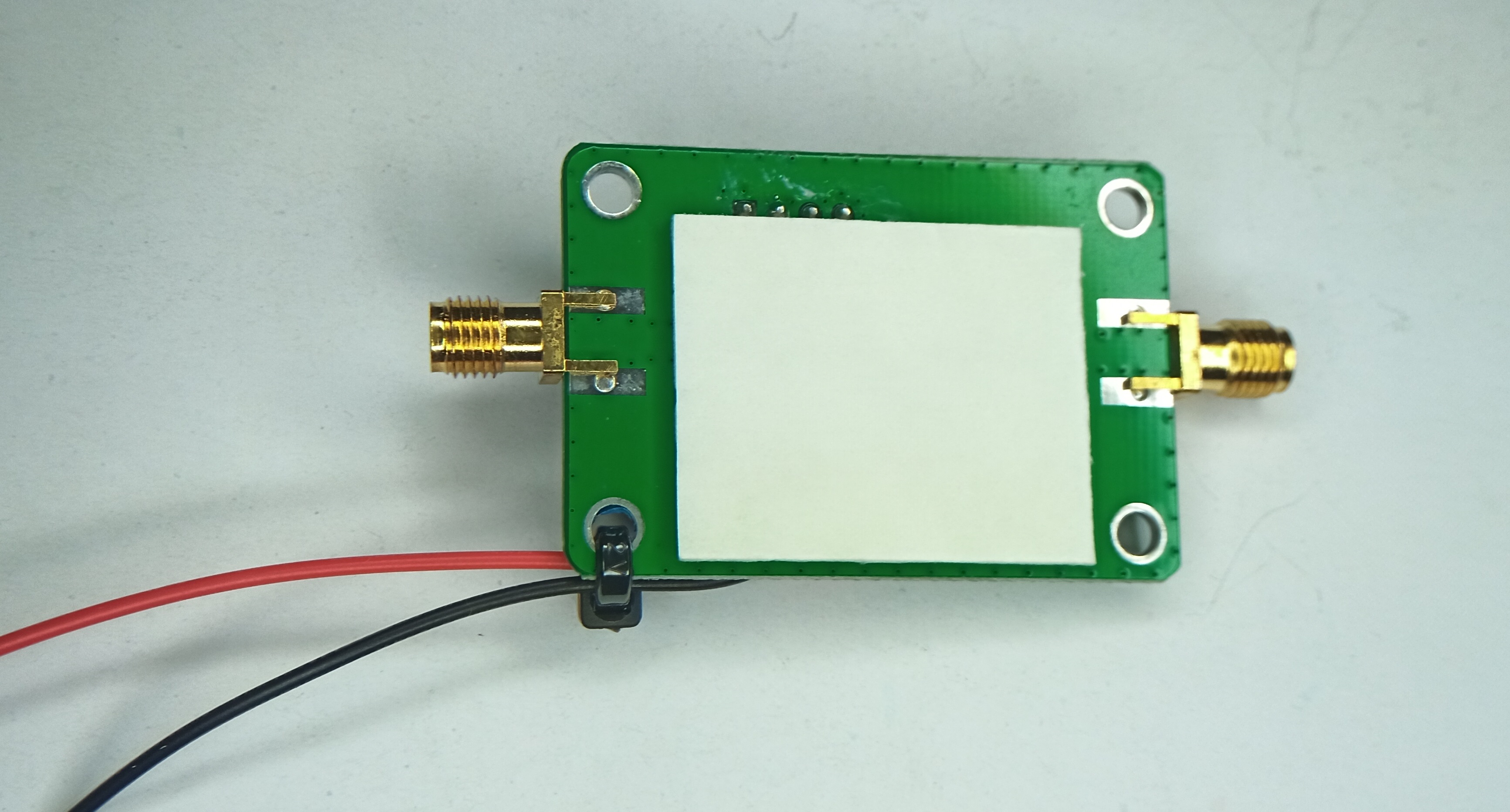
- Optional, but recommended, use foam type double sided tape to affix the amp board to the power pack, and zip tie the wires, apply tape to bottom of amp board:
 Stick amp onto battery pack and zip tie wires:

You can see, i had to solder a 0 ohm resistor vertically on my output signal path by the capacitor, as the far side pad came off while i was removing the old components. As i said before, rather fragile...
- Overview
- Why the PCIe CX Card
- Filtering
- Replace Timing Crystal
- Different Amplifiers
- Readouts
- The Various Assemblies
- Verified Crystals
- Overview
- AD8367 CX card mod
- Optional: BNC mod
- Optional: BNC direct mod
- AD8367 RMS board Mod
- AD8367 Filter Setup