-
Notifications
You must be signed in to change notification settings - Fork 32
rs5808 spi patch
The BOSCAM rx5808 modules is popular in the builder scene since it is small and cheap.
http://www.banggood.com/FPV-5_8G-Wireless-Audio-Video-Receiving-Module-RX5808-p-84775.html
The quality is not great, but OK.
It popularity leads to some developments like this project.
The basis of this project is the SPI interface for the modules.
Details of the used RTC6715 can be found here.
By default the freqency selection happen with 3 controll pins (CH1, CH2, CH3).
By enabling the SPI interface this 3 pins will become the SPI interface pins.
SPI has 3 pins:
-
CLK -
SELECT -
DATA
After the patch the mapping is the following:
| Default Pin | SPI Pin |
|---|---|
| CH 1 | DATA |
| CH 2 | SELECT |
| CH 3 | CLOCK |
The SPI mode is controll by the SPI_EN pin on the chip.
This pin must be set to HIGH to get SPI on.
Currently there are two version of the module (see printer backside):
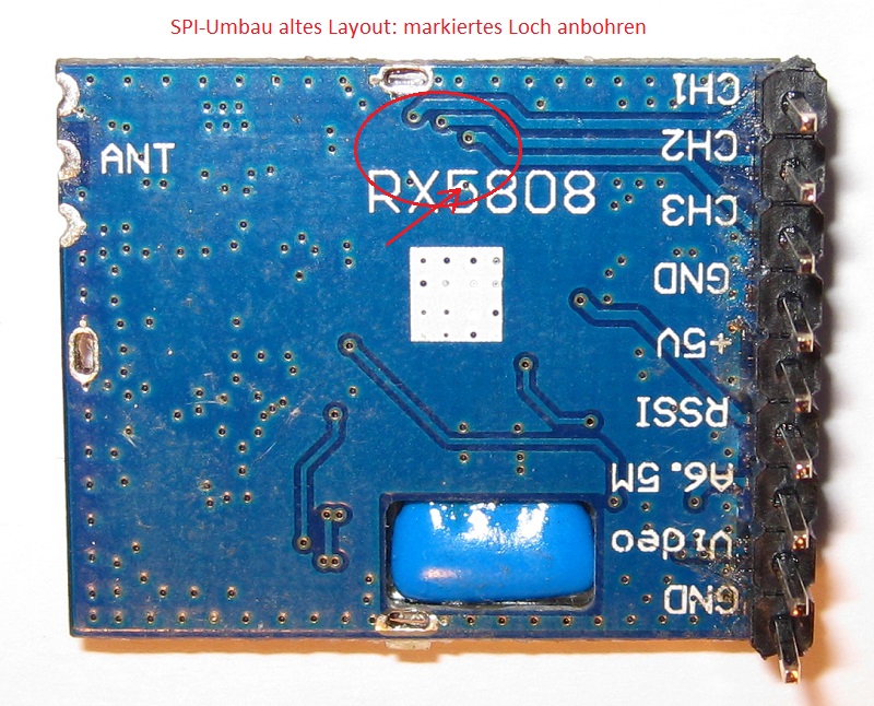
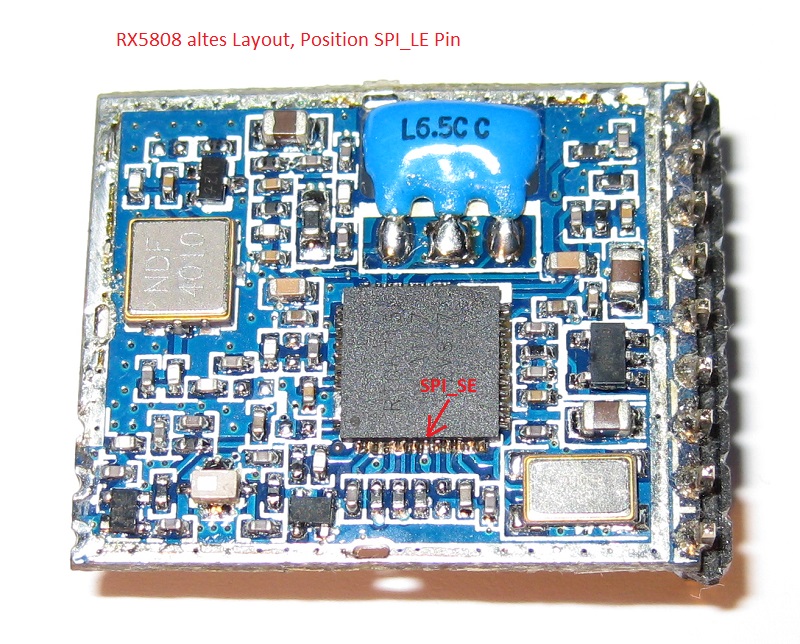
RX5808 (old version)
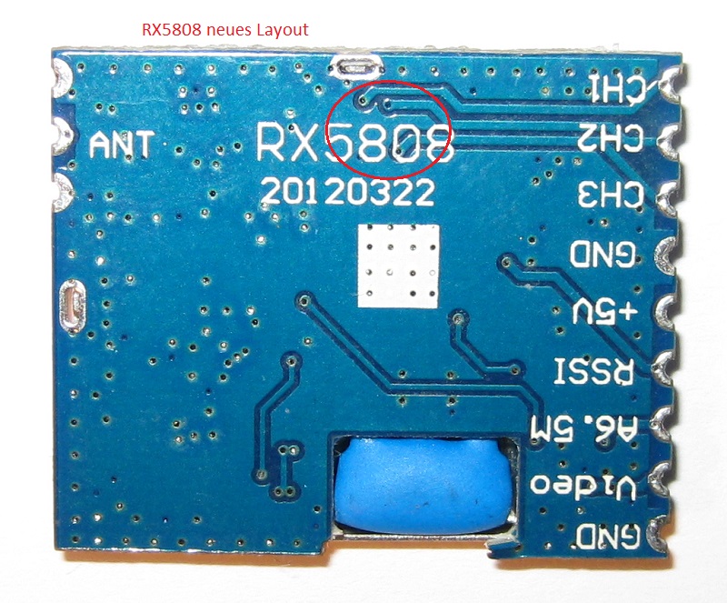
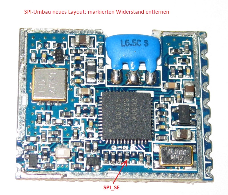
RX5808 20120322 (Version 22th March 2012)
Here the SPI_EN pin tight directly to GND. When the GND connection is loosen, an internal pullup resitor sets the required HIGH.
The follwing picture shows the module (with removed shield cover) from top an back.
For the patch a via must be drilled (CAREFULLY) to diconnect the GND from SPI_EN pin.
NICE: Shield cover must not be removed
BAD: This modules are no longer on sale
Check the images for details:

THE RED ARROW SPOTS THE VIA TO BE DRILLED

The new module has an pull down SMD resitor connected to the pin.
FOR THIS OPERATION THE SHIELD COVER MUST BE REMOVED.
The following pictures are showing the open module with the restor to be removed.


THE RED ARROW SPOTS TO THE RESTOR TO BE REMOVED