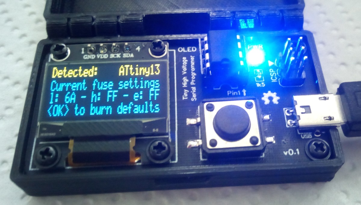
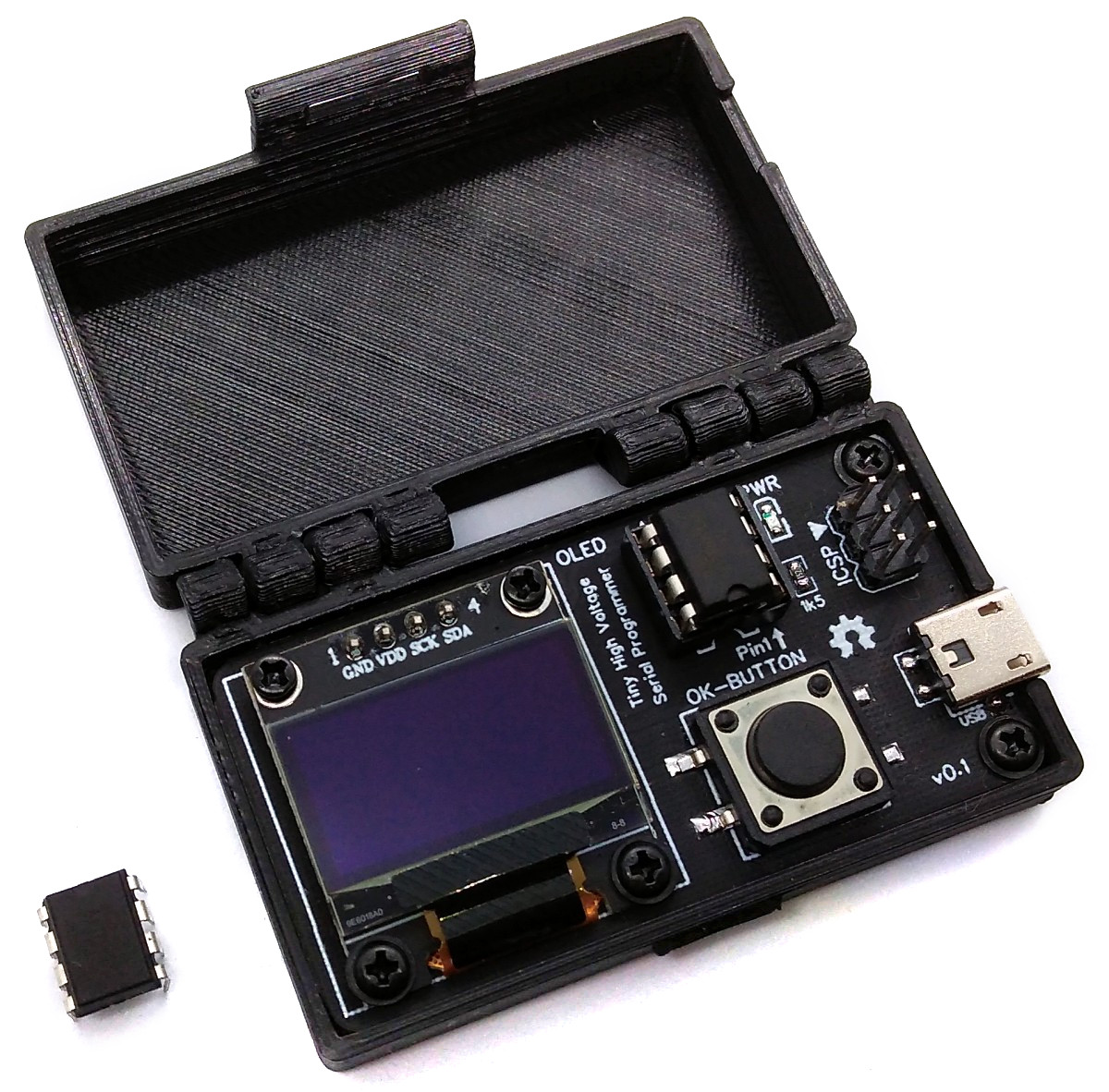
Stand-alone high-voltage serial programmer and fuse resetter for ATtiny 13/25/45/85. This project was superseded by the more versatile TinyCalibrator.
- Project Video (YouTube): https://youtu.be/2Q7D2RwkOMg
- Design Files (EasyEDA): https://easyeda.com/wagiminator/z-attiny84-tinyhvprogrammer
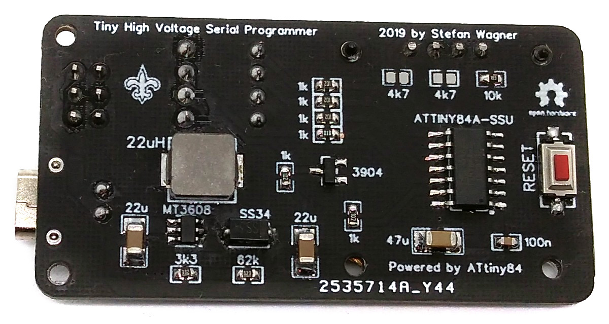
The TinyHVSP is supplied with 5V via a Micro USB connector. The ATtiny24/44/84 was chosen as the microcontroller for the TinyHVSP because it has the necessary number of GPIO pins. To generate the 12V for the High-Voltage Serial Programmer, an inexpensive MT3608 boost converter IC was used. The 12V is controlled by a BJT and applied to the RESET pin of the target ATtiny if necessary. The remaining programming lines to the target are protected against a short circuit with resistors. The user interface utilizes one button and a 128x64 pixels OLED display.
The code for the High-Voltage Serial Programmer (HVSP) is quite unspectacular. Simply put, for each action, a series of instructions are sent over the data lines to the target ATtiny and the corresponding response is read. The process and the instructions are well described in the data sheet.
The I²C protocol implementation is based on a crude bitbanging method. It was specifically designed for the limited resources of ATtiny10 and ATtiny13, but it works with some other AVRs (including the ATtiny24/44/84) as well. The functions for the OLED are adapted to the SSD1306 OLED module, but they can easily be modified to be used for other modules. In order to save resources, only the basic functionalities which are needed for this application are implemented. For a detailed information on the working principle of the I²C OLED implementation visit TinyOLEDdemo.
- Make sure you have installed ATtinyCore.
- Go to Tools -> Board -> ATtinyCore and select ATtiny24/44/84(a) (No bootloader).
- Go to Tools and choose the following board options:
- Chip: ATtiny24(a) or 44(a) or 84(a) (depending on your chip)
- Clock: 8 MHz (internal)
- Millis/Micros: disabled
- Leave the rest at the default settings
- Connect your programmer to your PC and to the ICSP header of the device.
- Go to Tools -> Programmer and select your ISP programmer (e.g. USBasp).
- Go to Tools -> Burn Bootloader to burn the fuses.
- Open TinyHVSP sketch and click Upload.
- Make sure you have installed avrdude.
- Connect your programmer to your PC and to the ICSP header of the device.
- Open a terminal.
- Navigate to the folder with the hex-file.
- Execute the following command (if necessary replace "t84" with the chip you use and "usbasp" with the programmer you use):
avrdude -c usbasp -p t84 -U lfuse:w:0xe2:m -U hfuse:w:0xd7:m -U efuse:w:0xff:m -U flash:w:tinyhvsp.hex
- Make sure you have installed avr-gcc toolchain and avrdude.
- Connect your programmer to your PC and to the ICSP header of the device.
- Open a terminal.
- Navigate to the folder with the makefile and the Arduino sketch.
- Run
DEVICE=attiny84 PROGRMR=usbasp make installto compile, burn the fuses and upload the firmware (change DEVICE and PROGRMR accordingly).
- Connect a 5V power supply to the micro USB port.
- Place the ATtiny13/25/45/85 in the IC socket. Use an SOP adapter for SMD parts.
- Press OK-button and follow the instructions on the display.
- TinyCalibrator
- AVR HVSP by Paul Willoughby
- AVR HV Programmer by Jeff Keyzer
- PiggyFuse by Ralph Doncaster
- I²C OLED Tutorial
- ATtiny24/44/84 Datasheet
- ATtiny13A Datasheet
- ATtiny25/45/85 Datasheet
This work is licensed under Creative Commons Attribution-ShareAlike 3.0 Unported License. (http://creativecommons.org/licenses/by-sa/3.0/)


