Esp 12F based board documentation
- Concept
- Dimensions and range
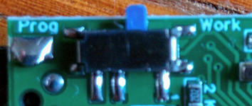
- Function of the switch
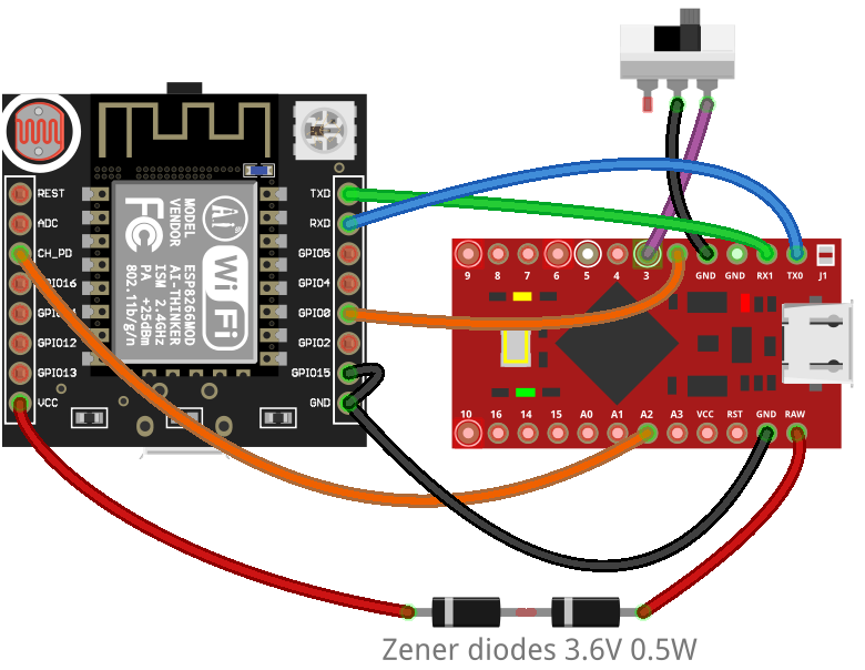
- Wiring
- LEDs behaviour
- Issues
- How to update
- Compability with other projects
- Additional info
- Video of assembling the board
- EasyEDA project
- Parts list
- Resources useful for making such boards
- Sale
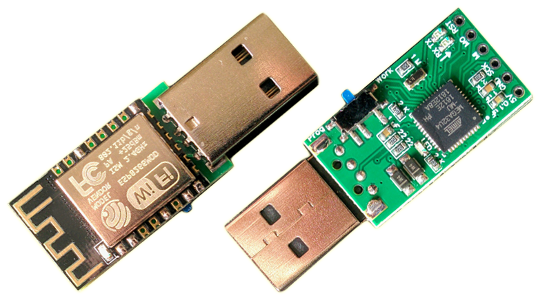
The board has 2 main parts:
- Atmega32U4 chip (the same chip found in boards like Arduino Pro Micro, CJMCU Beetle or Malduino). It is responsible for typing keystrokes.
- Esp-12F wifi module. It makes the communication between Atmega32U4 and mobile application possible.
Essentially it's a board that mimics CJMCU Beetle in this kind of setup but is shaped/wired to allow soldering Esp-12F to the back of it. It also has a switch.
PCB: 16x28.3mm (1.6mm thickness, I'd pick lower thickness but Esp-12F generates a lot of heat)
Whole device length: 44.7mm
Range: 14 meters
If you are familiar with wifi_ducky project you probably know that in order to update the Esp-12F bin file it is required to upload a separate/special code to Atmega32U4, meaning that a single update requires 3 actions:
- Upload of the separate/special code to Atmega32U4 using Arduino IDE.
- Upload of Esp-12F bin file through "Nodemcu flasher".
- Upload of the main Arduino code to Atmega32U4.
The function of the switch is to simplify this process. supremeDuck code already contains the "separate/special" code that is required to flash the Esp-12F, and runs it when the switch is turned into "Prog" position while powering the device. With the switch, update of Esp-12F code looks like this:
- Switch is set to "Prog" side (when device is unplugged).
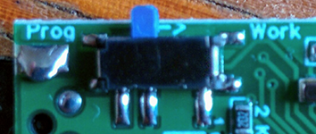
- Upload of Esp-12F bin file through NodeMCU Flasher.
- Switch is set back to "Work" side (when device is unplugged).
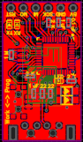
Full schematic is available at the EasyEDA project page. The wiring is equivalent to:
The blue LED of Esp-12F:
- lights up for 1 second at the begining of the supremeDuck code (it shows that the esp code is running properly)
- blinks quickly 3 times when it successfully handshakes with Atmega32U4
- stays off during normal operation (after 1 sec blink + 3 quick blinks for the handshake)
It also blinks once very quickly when esp is powered (regardless whether it's in normal or programming mode) and blinks rapidly when the bin file is being uploaded to it (using NodeMCU Flasher).
The green LED near Atmega32U4:
- lights up for 100ms after handshake with Esp
- lights up for 100ms whenever message was received from the mobile application (e.g. creating constant light effect when mouse is being moved)
2 yellow LEDs (TX and RX) are indicators of Atmega32U4 receiving or transmitting data through serial (USB).
In the prototypes I ordered from OSH Park these were connected to GND (meaning they are normally turned on), the current design of the board has them connected to VCC (meaning they are normally turned off).
Correct startup preview:
⚡ Occasional lag spikes in mouse movement especially shortly after connecting with access point.
It seems like it's caused by the Esp-12F itself. I also noticed that the supplying source of the Esp-12F really matters. I ordered Esp-12F boards from 3 different sources. The boards from this source ("Brand Name: AITEXM ROBOT") were acting very slow, making the device very frustrating to use, almost unusable.
⚡ Esp-12F gets quite hot.
It doesn't seem to affect its' operation. I intentionally left this board plugged in for few hours just to make sure it doesn't fail over time due to heat.
https://github.com/michalmonday/supremeDuck/wiki/How-to-update
To use this board with other projects it is required to upload the sketch below to it:
int program_pin = 2; // 2 of Arduino Pro Micro, SDA, PD1 (19 of Atmega32u4) - pin controlling the state of GPIO 0 (Esp-12F pin)
int enable_pin = 20; // 20 of Arduino Pro Micro, A2, PF5 (38 of Atmega32u4) - pin controlling state of "EN" (Esp-12F pin)

void setup()
{
  Serial1.begin(115200);
  Serial.begin(115200);
  pinMode(enable_pin, OUTPUT);
  pinMode(program_pin, OUTPUT);
  digitalWrite(program_pin, LOW);
  digitalWrite(enable_pin,HIGH);
}

void loop()
{
  while(Serial1.available()){
    Serial.write((uint8_t)Serial1.read());
  }

  while(Serial.available()){
    Serial1.write((uint8_t)Serial.read());
  }
}
That will turn the Esp8266 into programming mode once the board is replugged, so it will be possible to use NodeMcu flasher or esptool just as suggested in wifi_ducky or ESPloitV2.
You can notice that the code is very similar to the ones used in wifi_ducky for example, but it has pins defined to match the connections on the PCB (where pin 2 controls the GPIO 0 and pin 20 controls the "EN" pin of the Esp, both of them are turning the Esp into programming and working modes).
Side note:
The purpose of the switch on the board is to automatically run the code above without the need to upload it when we want to reflash the Esp, that is implemented in the supremeDuck code. I suggested to use the same method in wifi_ducky but I don't know if it will be added. You can implement it yourself though, the suggestion includes all the instructions on how to modify the "arduino_wifi_duck.ino" from wifi_ducky project.
The MO, MI and SCK pins can be used as I/O pins on Arduino Pro Micro
MO = pin 16 of Arduino Pro Micro
MI = pin 14
SCK = pin 15
The switch also can be reprogrammed to do something different, it connects pin 3 of Arduino Pro Micro with GND when it's switched towards "Prog" (it should be used as INPUT_PULLUP). For example:
pinMode(3, INPUT_PULLUP);
if (digitalRead(3) == LOW ) {
// switch is on, programming mode
}
else{
// switch is off, working mode
}https://www.youtube.com/watch?v=lb6cKvJvXkY
See this for additional info about flashing bootloader (useful if you're planning to create similar board yourself).
Notes:
⚡ In the video I placed solder paste on a piece of paper. It is better to put it on a piece of plastic like credit card (because paper soaks the moisture, making the paste dry quicker).
⚡ At 01:20 of the video I am using hotair station with the board positioned over the table without any heat resistant mat. Doing this will most likely damage the table (which happened to me few times, I treat it as a workbench though).
It is a good idea to use microscope to check the position of the Atmega32U4 chip before heating it up. Applying the right amount of solder paste, positioning of the chip and getting rid of solder bridges is the biggest challenge when creating these I think. Too much solder paste leads to many solder bridges, not enough solder paste may lead to lack of connection or cold solder joint (which is worse than lack of connection) and in such case it may be necessary to re-solder the pins using normal soldering iron. The images below show how the pins should be positioned, it also shows that £10 microscope can be very useful. It is really difficult to see how pins are aligned with naked eye. The structure of solder paste can be noticed, it consists of small "balls", it's very important to wear gloves when handling it because these "balls" get inside the skin and cause serious, permanent health issues.


https://easyeda.com/michalmonday17/supremeduck_wifi
All parts are 0603 except zener diodes that are 1206 (I couldn't find smaller ones that would provide as much current).
I recommend using OSH Park, for $3.40 (including shipping) they delivered the 3 copies of the first version in 18 days.
It is the most expensive of the parts, you could as well buy CJMCU Beetle and desolder the chip, this way you'd also get some LEDs, 22-Ohm resistors, 1M resistor and oscillator.
- Zener diodes (2x BZT52C3V6 3.6V 0.5W 1206)
-
Resistors
- 2x 22-Ohm (for USB data lines)
- 3x 2k-Ohm (for LEDs, I don't like them being too bright but you may choose smaller value especially if you will use some kind of case)
- 1x 1M-Ohm (for Oscillator)
-
Capacitors
- 2x 1uF
- 1x 0.1uf(100nF)
- Mini switch (#DSC0011)
This switch became hard/expensive to get. I added design with alternative switch that is cheap and common (MSK-12C02)
- Oscillator (16MHZ CSTCE16M0V53-R0 3.2*1.3 SMD Crystal)
- USB 2.0 Male connector (standard "through-hole", "90 degrees")
- LEDs (personally I'm going to use green one as the main LED and most likely yellow for TX and RX leds)
- toothpick (for placing solder paste on the PCB)
https://github.com/michalmonday/supremeDuck/wiki/Resources-useful-for-making-PCBs
My website - http://monday.pythonanywhere.com/
Tindie - https://www.tindie.com/products/michalmonday/wifi-badusb/