-
Notifications
You must be signed in to change notification settings - Fork 118
91 (References) LTE Modems
With the addition of LTE wireless connectivity, the Intel Aero platform enables a broader range of use cases. Your drone can now be controlled remotely anywhere there is a cellular signal. And data can be transmitted over the LTE wireless link to provide continuous connectivity.
With the v1.5.1 software update, the Intel Aero Compute Board (part of the Intel Aero Ready to Fly Drone) enables users to install LTE modem devices into the M.2 interface and configure their drone for communications over LTE.
Starting with version 1.5.1, LTE modem capabilities are enabled via the M.2 connector located on the top-side of the Intel ® Aero Compute Board. The v1.5.1 release requires updates to both the BIOS and BSP. The updated BSP contains new modem management software and the updated BIOS enables the M.2 connector.
We recommend using LTE modems based on Intel’s XMM 7160 chipset. Products include the Telit LN930 and Sierra Wireless AirPrime* EM7345 which are certified for use across the globe. Please refer to the modem manufacturer’s product literature for specific capabilities
NOTE: It is the pilot’s responsibility to obtain the necessary permits from both the government regulatory agencies as well as the cellular service providers.
- Purchase all necessary items listed in the next section "Detailed Hardware Installation"
- Repurpose the original WiFi antennas for use with the LTE modem
a. If Wifi is needed, follow Instructables for adding an extended-range WiFi solution - Insert the LTE modem into the M.2 connector
- Secure the LTE modem using the 2mm hex nut
- Insert the SIM card into the SIM card tray and slide it into the SIM slot slowly
- Download and install v1.5.1 software update
a. Update the BIOS
b. Update the BSP - Configure Modem Manager to establish connectivity
To preform the LTE modem hardware installation, you will need to purchase the four items shown in Figure 1:
- LTE modem module
- Nano SIM card
- Tray to hold the nano SIM card
- 2mm hex nut
Links to online retailers where these items can be purchased are found at the end of these instructions.
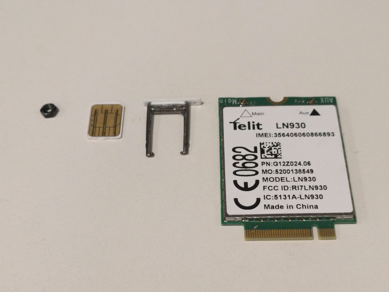
Figure 1. Required Hardware
The LTE modem will be installed into the M.2 connector which is located on the top side of the Aero Compute Board, adjacent to the 80 pin I/O Expansion Connector. Use the 2mm hex nut to secure the LTE modem module to the mounting post near the heat sink.
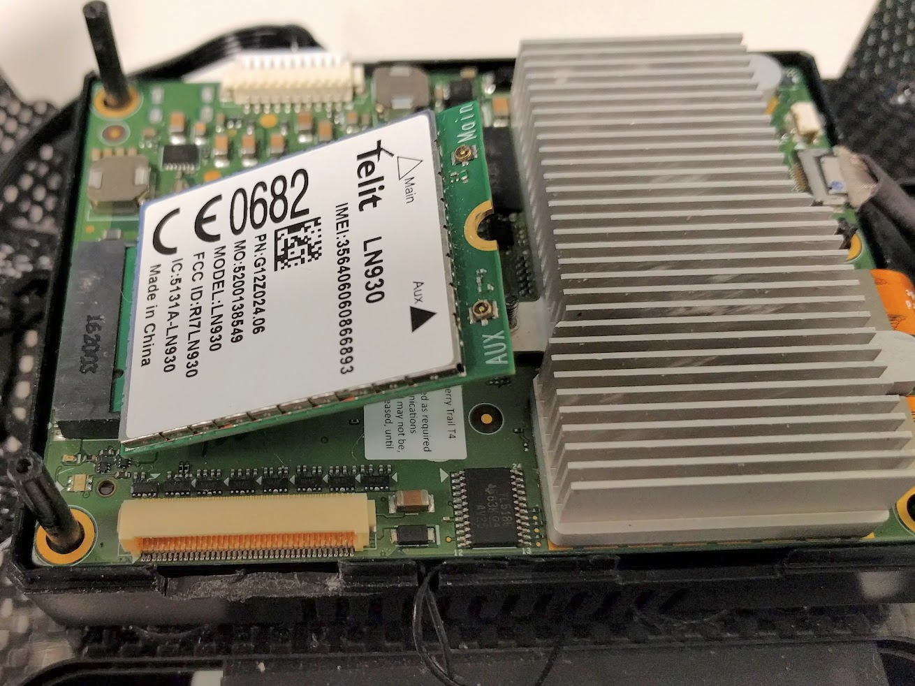
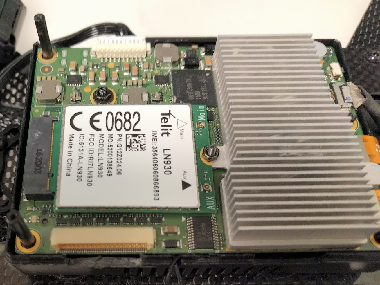
Figure 2. Insert modem into M.2 and secure it with the 2mm hex nut
When installing the LTE modem, two antennas are required for proper operation. Both the Intel Aero Ready to Fly Drone and the Intel Compute Board are shipped with two WiFi antenna. These two antennas appear as "wings" attached to the sides of the plastic enclosure. The WiFi antennas will be re-purposed for use with the LTE modem.
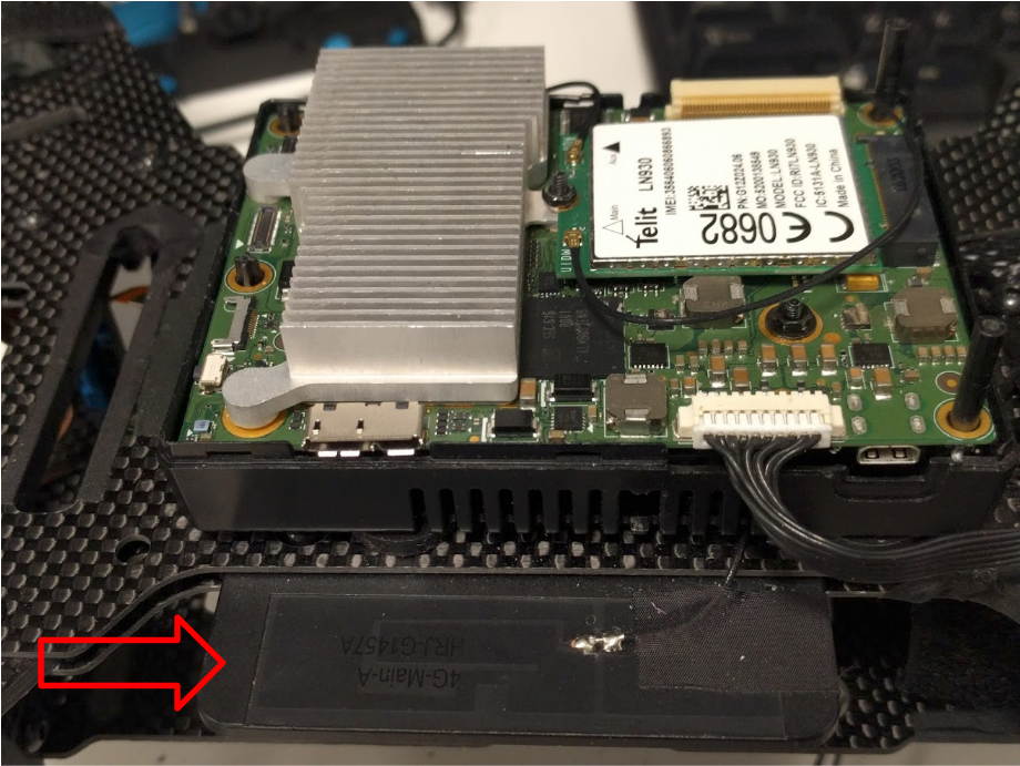
Figure 4. Image showing location of the wings
if WiFi communication is not needed, then carefully disconnect the antennas micro SMA connectors from the WiFi module on the bottom of the Aero Compute Board and connect them to the two micro SMA connectors on the LTE modem. These are very small connectors. The antennas will "pop" off. Be gentle and careful when removing them. After connecting them to the LTE modem, verify a good connection is made by rotating the antenna on the micro SMA connector to verify that it can rotate freely. If the antenna does not rotate freely, then the antenna is not properly seated on the micro SMA connector.
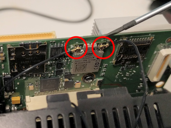
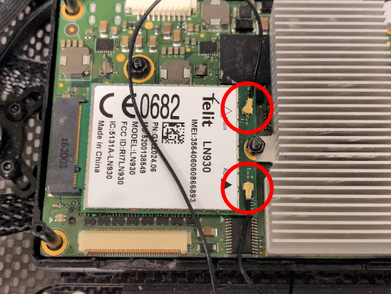
Figure 5. Image on the left shows the removal of the antenna from the WiFi module underneath the Aero Compute Board. Then on the right they are attached to the modem.
If both WiFi and LTE modem functions are required, we recommend replacing the Intel Aero Ready to Fly Drone's WiFi antennas by following our "Instructable" which will extend the range of the drone's WiFi radio. This will allow you to then use the original WiFi antennas for the LTE modem as described above.
The SIM card slot is located on the bottom side of the Compute Board underneath the 80 pin I/O Expansion Connector. You will notice that when the SIM card is inserted, the SIM tray sticks out more than allowed by the enclosure which prevents the Compute Board from being fully seated. To accommodate the SIM tray, the opening for the SIM card must be widened. This requires a modification to the bottom half of the plastic enclosure.
Using a tool of your choice (X-Acto knife works well), make an opening in the plastic enclosure for the SIM tray that is approximately 16mm x 5mm. This will allow enough room for the SIM tray to sit comfortably within the enclosure and also allow easy access for extracting the SIM card.
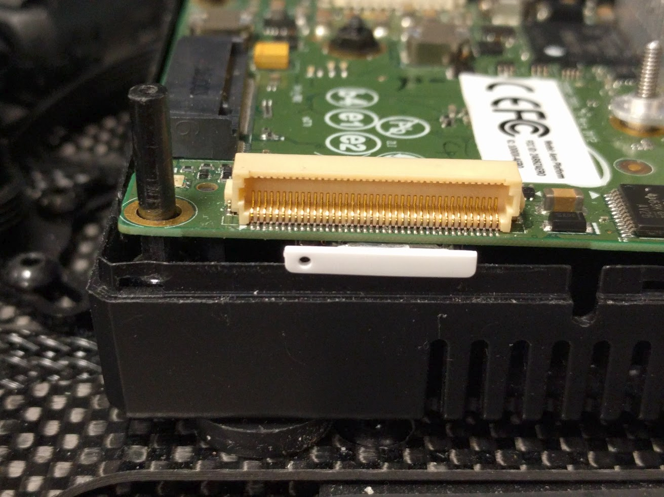
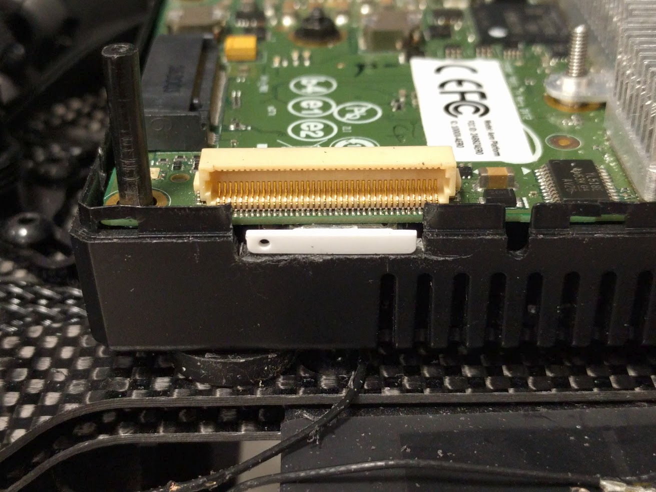
Figure 6. Image on the left shows how the SIM tray interferes with the plastic enclosure. Image on the right shows the SIM tray fits within the plastic enclosure after modifications.
Follow these instructions for downloading and installing the software update. Both the BSP and BIOS must be updated to at least the following versions
- BSP v1.5.1
- BIOS v01.00.13
Note that the Aero Ready to Fly Drone will also require the flight controller firmware to be updated as well. Review the Aero software release notes for details.
After updating, open up a SSH terminal by connecting to Aero's WiFi Access Point (refer to this wiki ). Modem Manager (replaces Connection Manager on previous Aero BSP releases) should automatically detect the installed LTE modem and enumerate it as Modem 0. Query the modem info below.
# mmcli -m 0
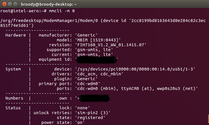
If the LTE modem is not detected, please double check that the modem is seated securely and the SIM card is properly inserted. Take precautions as the SIM card can potentially slide out due to airframe vibrations while in flight.
This is a good point to verify that the SIM card is properly recognized and is not locked. This can be found in the Status section reported above. If the SIM card is locked, contact your carrier for unlock instructions.
lock: `none`
state: `registered`
An APN must be set to correctly to access the public internet. Below are a few carriers in the U.S. and their corresponding APN.
- AT&T - "phone"
- Verizon - "vzwinternet"
- Tmobile - "fast.t-mobile.com"
- Sprint - "cinet.spcs"
APN name can be updated using the command below.
# nmcli con modify modem gsm.apn <name>
Reboot the system so that the configuration will take effect. With the previous "mmcli -m 0" command, find the bearer number from the output. Execute the following to show the details of the IP addresses.
# mmcli -b <bearer number>
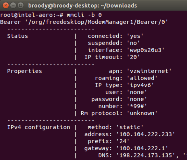
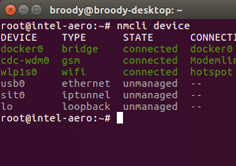
Below you can see the device "cdc-wdm0" with connection name "modem" is in the connected state.
# nmcli device
Verify internet connectivity by pinging your favorite website.
# ping www.intel.com
By default, QGC communicates directly with Aero when connected to Aero's WiFi Access Point. However, when the drone is on LTE, a direct connection is non-trivial as both the drone and PC can be behind multiple layers of NATs/firewall.
There are several ways to circumvent this. In the options described below, a cloud server is used to help route packets between the drone and PC. These servers are inexpensive and easy to set up, like Amazon’s AWS and Google’s Compute Engine.
On the Intel Aero Ready to Fly Drone (aka Aero RTF), mavlink-router runs locally to handle routing packets between the flight controller and different IP endpoints. But we can also deploy another instance of mavlink-router in the cloud to handle routing just IP traffic. Both the drone(s) and QGC are then connected to this cloud based mavlink-router and communication is established. One benefit of using this method is flight logs are stored automatically in the cloud, so in case of fly-aways a copy of the logs can be retrieved. This method also scales well with one-to-many use cases.
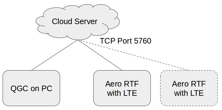
- Obtain access to a Linux based cloud server and note its external IP
- Configure the server's firewall to allow TCP traffic on port 5760
- Access the server through a terminal. Build and deploy mavlink-router
- On the Aero RTF, edit /etc/mavlink-router/main.conf and append the following line: [TcpEndpoint LTE] Address = XX.XX.XX.XX (replace with server ip) Port = 5760
- Reboot the drone. Mavlink-router will automatically try to connect to the server
- In QGC, under the Comm Links tab add an additional TCP connection with the server IP and port number
- Click connect. You should now be communicating over LTE!
This method is simpler to deploy and requires no additional software on the server. The server effectively acts as a bridge between the PC and drone. Steps below assumes AWS cloud service.
- Obtain access to a Linux based cloud server and note its external IP
- Configure the server's firewall to allow TCP traffic on port 5760
On PC execute:
# ssh -i .keys/AmazonCloud.pem -L 5760:localhost:5760 -N <AWS User>@<AWS Instance>.compute.amazonaws.com
On Aero RTF execute:
# ssh -i /home/root/.keys/AmazonCloud.pem -R 5760:localhost:5760 -N -f -T <AWS User>@<AWS Instance>.compute.amazonaws.com>/var/log/aero.log 2>&1
These links are examples of where to purchase the required hardware. Intel does not advocate any specific retailer. Use these links as general reference only.
| Item | Link |
|---|---|
| LTE Modem |
Telit LN930 Sierra Wireless AirPrime EM7345 |
| Nano SIM card | Purchase from local wireless carrier |
| Nano SIM card tray | Link |
| 2mm hex nut | Link |
For all issues not addressed in this document, please submit them to the Aero online Community Support Forum
All product and company names are trademarks or registered trademarks of their respective holders. Use of them does not imply any affiliation with or endorsement by them.
Latest Software (BIOS & OS image) BSP Released: v1.6.1 on 2017-12-18
Important: This repository is no longer being maintained
- About Intel Aero
- Initial Setup
- First Flight
- Ubuntu* installation
- Video Course - Autonomous Drone Engineer
- Intel Aero Ecosystem