Author: Claas Lendt (I'm tweeting @claaslendt)
Last modified: 10.06.2023
Note: This is a living documentation and will be continuously extended and reviewed.
My PhD research focusses on the development and validation of new computational methods to monitor human physical behaviour based on the acceleration of the thigh. One key area of my research is the estimation of activity-induced energy expenditure. In other words, I want to develop an accurate algorithm to estimate how many calories are burned when someone is physically active. To achieve this goal, I need data to develop my algorithm and see how accurate it really is. These data include a primary reference for the energy expenditure (also considered ground truth), raw triaxial acceleration of the thigh and further references from existing methods.
One particular method I want to compare my algorithm against is the wearable system proposed by Patrick Slade and colleagues (Link to the paper: Slade et al. 2021 - Nature Communications). It comprises two inertial measurement units (IMUs) on the thigh and the shank, a Raspberry Pi as the computing unit, a rechargeable battery and a regression model. The estimation of the energy expenditure is based on a linear regression model with accelerometer and gyroscope data as inputs. Their novel approach uses stride segmentation of the IMU data and then performing the energy expenditure estimation on discrete stride cycles. This is super interesting, given that most other computational methods are based on some form of regression model with an aggregated measure of the acceleration over a fixed time interval. Overall, a highly innovative and quite accurate approach!
It seems like the wearable system from Patrick Slade et al. is a good candidate to compare my future estimations against! So I decided to recreate the system based on the information given in the paper and its supplementary documents. It's been quite a journey, given that I had almost zero knowledge on the Raspberry Pi, I2C addresses or 3D printing at the start of this project.
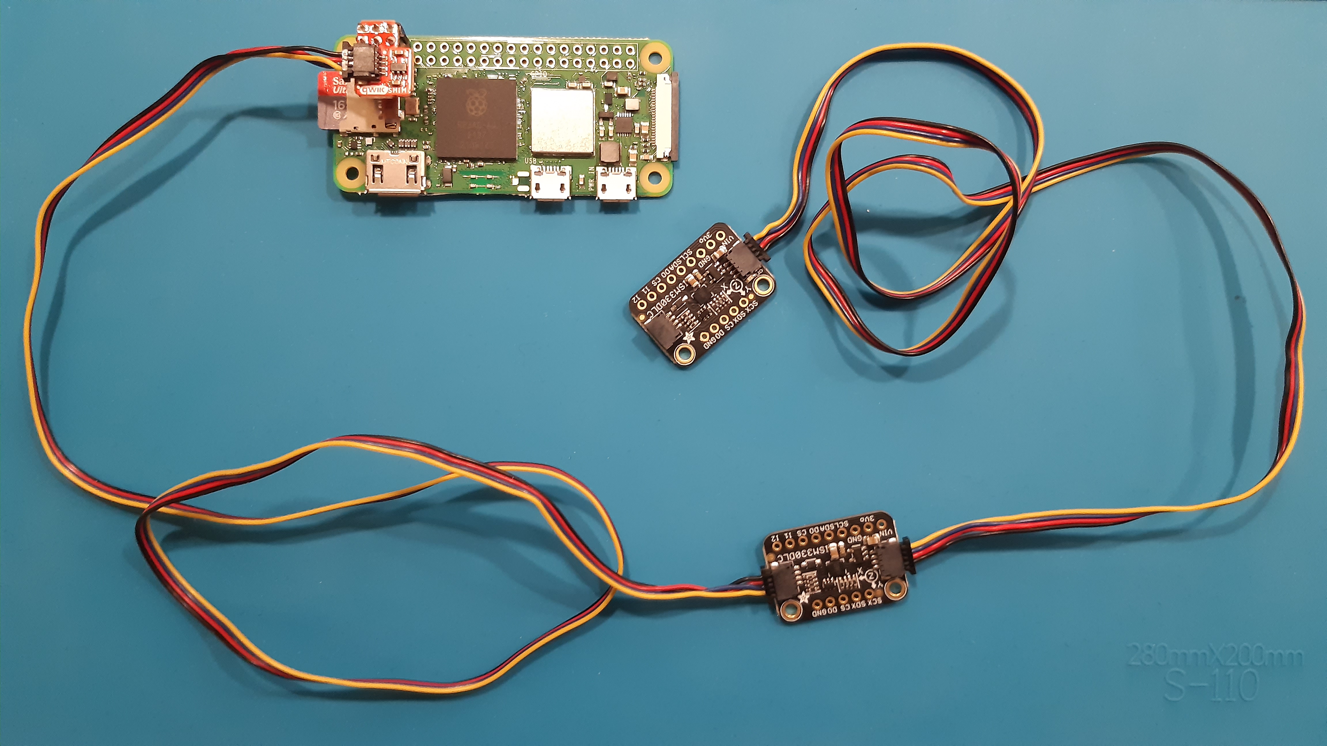
To start with, I chose a Raspberry Pi Zero 2 W as my computing unit. It's quite compact compared to the Raspberry Pi 4 and still powerful enough to allow the collection and processing of the IMU data. Further, it can easily run Python code. I haven't used any Raspberry Pi before, but it was extremely easy to get started. There are great documentations available online (see raspberrypi.com/documentation) and setting up the mini-computer can be done in short time.
As for the IMUs, I chose the Adafruit ISM330DHCX sensor breakout boards. These sensors allow to capture a range of ±16 g of acceleration and up to ±4000 dps. The breakout boards are great because they can easily be connected to a computing unit using the integrated STEMMA QT connectors. In my case, the Raspberry Pi and the IMUs are connected using 50cm STEMMA QT (also called "Qwiic") connection cables and a SparkFun Qwiic SHIM adapter for the Raspberry Pi. At the beginning, I thought I could create the system without the need for any soldering. But I was wrong. Thankfully, I got support from our electronics lab in soldering the pins to the Raspberry Pi and the adapter as well as setting the alternative I2C address for the IMU at the shank.
The final component is an 10.000mAh USB rechargeable battery to power the system during mobile use. The battery is simply connected to the Raspberry Pi using a short USB cable (USB-A to micro-USB). I went with the Ansmann PB320PD.
Figure 1. The Raspberry Pi Zero 2 W, the two Adafruit IMUs and the STEMMA QT/Qwiic connections using the SparkFun SHIM adapter on the Raspberry Pi.
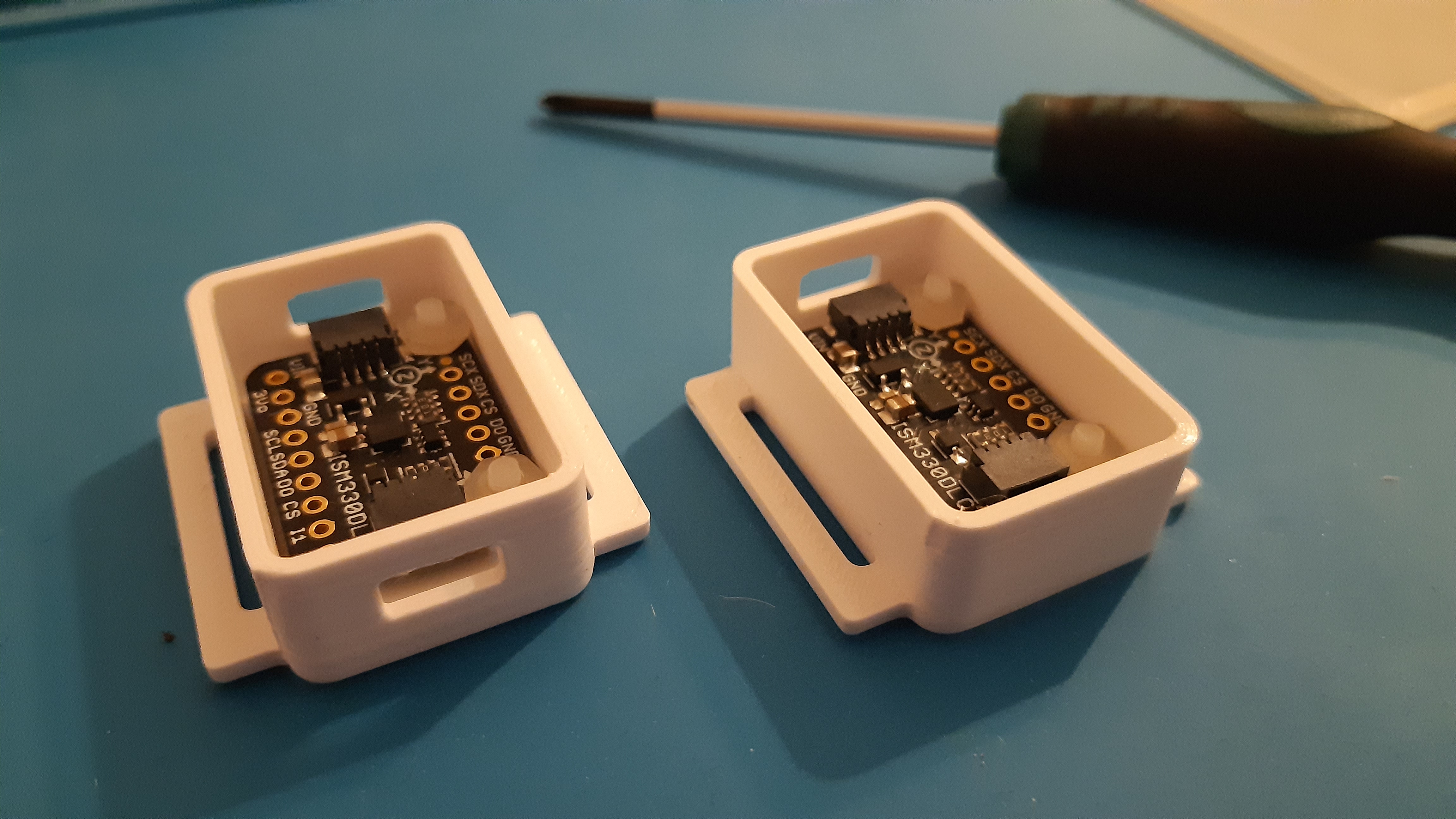
The two IMUs and the Raspberry Pi need to be attached to the body and be protected from receiving any damage during movements. I decided to 3D print my own cases since there wasn't any simple solution available. My starting point was the great article 3D Printed Case for Adafruit Feather and I iteratively developed my own version to fit the Raspberry Pi Zero and a smaller case for the IMUs. I used Autodesk Fusion 360 for the modelling of the individual parts, which required some time to learn the software. A much easier and no-cost option may be Autodesk's Tinkercad.
Each case consists of a base unit and a top. The connection cables can be attached through the small holes. The Raspberry Pi and the IMU boards are attached to the case using small plastic screws (M2.5) and hex nuts. I am also sharing the files used for printing within the 3d_printing folder.
Figure 2. The two cases for the IMUs with the screws and hex nuts fixating the IMUs to the case. The additional wings on the cases are used to attach the cases with additional elastic straps (see below).
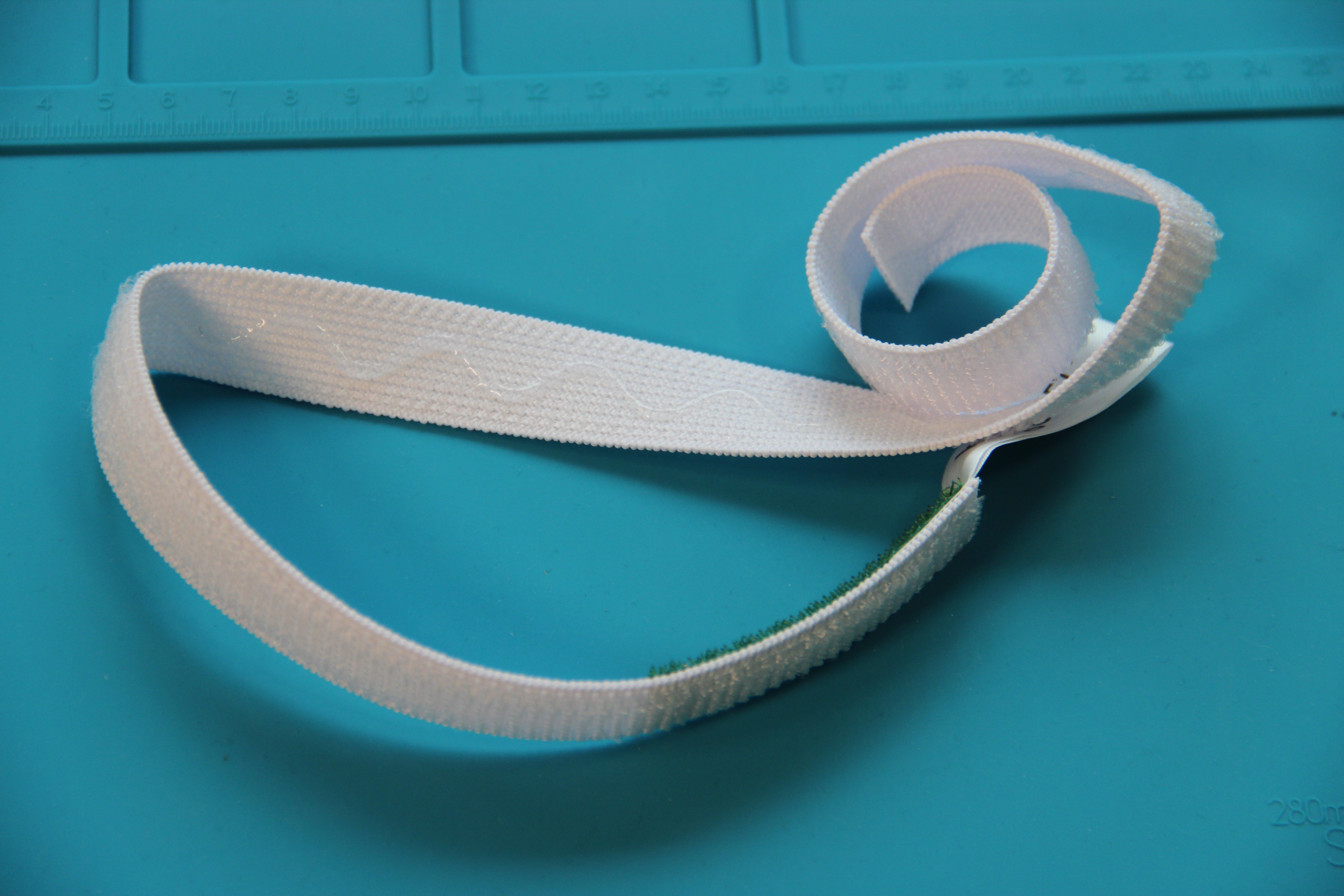
I did quite some experimenting with different elastic straps to attach the sensors to the thigh and shank as I wanted them to be lightweight, comfortable and not slipping too much. At the end, I found some elastic straps which are used to attach urine drainage bags (see MedlinePlus: Medical Encyclopaedia) and they work great! The strap has a layer of silicone rubber which prevents any slippage during movements of the leg and can easily be attached using the velcro. The PZN (German Medical Product ID) for these particular straps is 08913533.
Figure 3. The medical straps used to attach the sensor units to the shank and thigh.
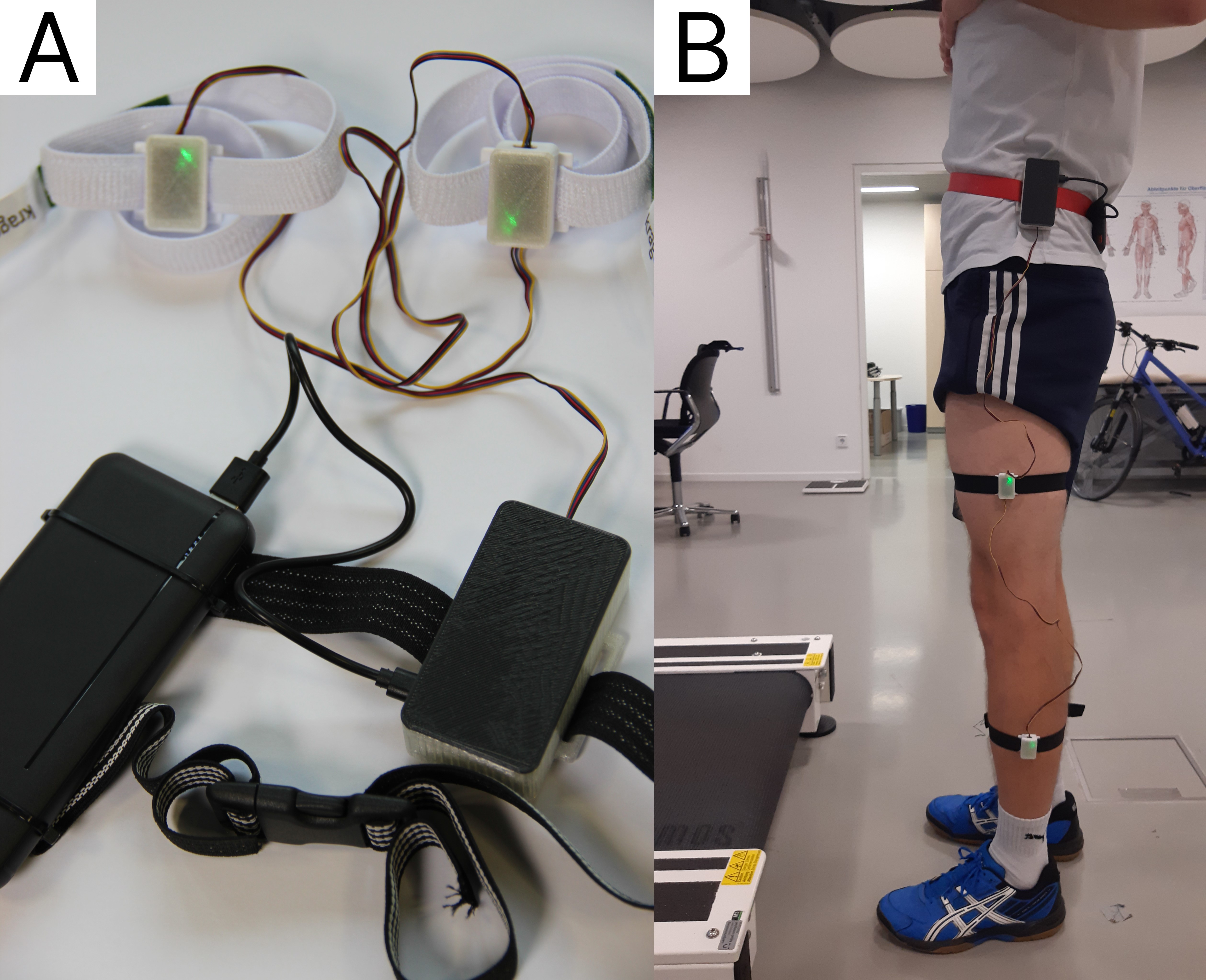
When everything is put together, the Raspberry Pi and the battery are attached to the waist using an elastic belt with a quick-release. The two IMUs are attached to the shank and thigh. The system has been quite comfortable during my piloting (walking and running on a treadmill as well as cycling on an ergometer).
Figure 4. The left (A) shows the complete system with the battery (lower left) connected to the Raspberry Pi (lower right) via USB. The Raspberry Pi is connected to the IMU at the thigh via Qwiic cable. Finally, the two IMUs are connected using another Qwiic cable. The system is attached to the left leg (B).
Patrick Slade is openly sharing the Python code to run his model on GitHub / Zenodo (DOI: 10.5281/zenodo.4891703). It only requires a single code file and the model weights, which are stored within a .csv file. The two files can easily be transferred on the Raspberry Pi and run using the preinstalled Thonny Python IDE.
There is a great tutorial using Google Colab: Tutorial - Estimating Energy Expenditure and a webinar by Patrick Slade (Stanford mobilize - Webinar: Estimating Energy Expenditure During Exercise Using Wearable Sensors). I can highly recommend both resources to further understand the system and modelling approach. Thanks to Patrick for putting all these great resources out there and making the model open-source! 🚀
I want to thank Thomas Förster for supporting me with the soldering, the MakerSpace Bonn for providing me with all the knowledge and tools for 3D printing and Theresa Braun for the overall support.


