Update 2022
Wow it's been a while.
Its been a bit over 6 years (maybe more by the time you're reading this) since I made this controller and the build log below. That also means there's that many years worth of newer projects and code out there for building music game controllers. Just to make it very clear, most (if not all) of the code in this repository is outdated and I highly recommend looking at some better/newer resources (code and build logs) if you are planning to try a similar project:
- https://consandstuff.github.io/ (active community, especially recommend checking out the discord)
- https://github.com/knuckleslee/RhythmCodes (will probably work right out of the box)
- https://rhythm-cons.wiki/w/Controller_Code (general purpose rhythm game controller code)
- https://github.com/MHeironimus/ArduinoJoystickLibrary/ (general purpose joysticks code
- https://github.com/speedypotato/Pico-Game-Controller (for the Pi Pico, I personally bought one)
I'm glad that many people have found this repository useful. Keep making cool stuff!
Beatmania IIDX and Sound Voltex hybrid controller running on Arduino Due
Imgur album: http://imgur.com/a/iJoK6
Arduino DUE code targets arduino ver 1.6.4, 1.6.5 onwards added pluggable HID which breaks the SAM libraries
Arduino Leonardo code in /leoo/ targets arduino ver 1.6.8 but should work with versions upward of 1.6.5. /leoo/leoo/ contains code for 9 key + 9 led pnm controller, /leoo/leovx/ contains code for 7 key + 2 lq encoder (<=50ppr) voltex controller, /leoo/leohq/ contains code for 7 key + 2 hq encoder (>=50ppr) volltex controller.
For a controller for both Lunatic Rave 2 and K-shoot mania at once (as seen in the youtube video), use a arduino DUE. Download the SAM core with version 1.6.4 and setup as seen in the Software section.
If you rather use a leonardo, you have 3 options:
- Controller with 9 buttons and 9 LEDs as seen in /leoo/leoo/
- Controller with 7 buttons and 2 low quality encoders as seen in /leoo/leovx/
- Controller with 7 buttons and 2 high quality encoders as seen in /leoo/leovxhq/
Just open the .ino file with the latest arudino version and download.
- Beatmania Buttons x9
- Beatmania layout requires two rows of 3 and 4 vertical keys + 2 utility buttons
- Voltex layout requires two rows of 4 and 2 (horizontal) keys + 1 utility button
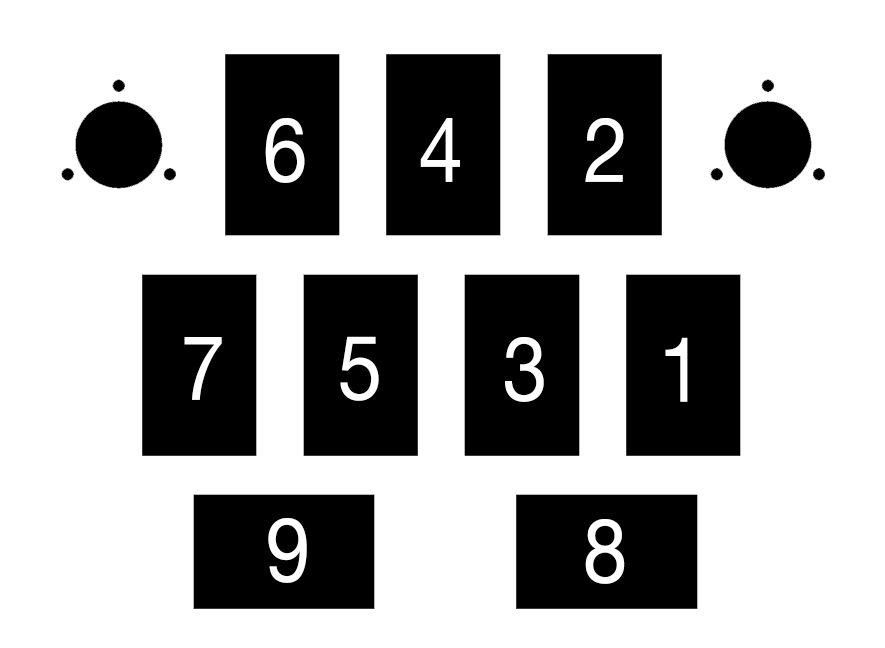
- Total 9 buttons, top row 3 vertical, middle row 4 vertical and bottom row 2 horizontal
- 9x White Buttons purchased via Taobao, $10 SGD w/o shipping, (Search Listings)
- One "button" comes with colored plunger, black main chassis with screw-threaded hollow shaft, accompanying nut for said shaft, extra rectangular housing for padding below, microswitch, microswitch LED saddle/chassis connector, LED housing and spring, all which are detachable
- Replacing microswitches invloves pulling out microswitch saddle and replacing the microswitch
- LEDs in the LED saddle may not all be same polarity, be sure to test and reverse LED polarity by pulling out and reinserting LED housing
- Custom LEDs can also be used by replacing the LED in the housing with your own LEDs
- LEDs are in theory rated for 12v, but the microcontroller can only supply 3.3v. Be sure to use a transistor or other power supply if you want full brightness.
- Rotary Encoders x3
- Beatmania layout requires 1 turntable, KOCs use an optical encoder, but a rotary encoder is used here for consistency in purchasing
- Voltex layout requires 2 knobs for VOL-L and VOL-R control
- 24ppr encoders should suffice to give a resolution of 96 points per 360 degrees, but higher resolution encoders (300, 600 ppr) are accounted for in this project
- 3x 600ppr Encoders purchased via Taobao, $25 SGD w/o shipping, (Search Listings)
- Microcontroller
- Arduino DUE used due to:
- High clock rate
- Interrupt capability on all pins (other Arduino boards only have 2-4 interrupt pins, insufficient for 4x reading of 3 different rotary encoders which need at least 6 interrupt pins)
- Native USB functionality, custom HID descriptor is used via modifying core libraries (See Software Section)
- Purchased a clone from Shenzhen Hua Qiang Bei, $20 SGD\
- Other clones of DUE board should be readily purchasable online
- Arduino DUE used due to:
- Breadboard and jumper wire
- Crimp receptacles
- Removable connectors which can be plugged in and out of microswitches on buttons
- Eliminates need to solder directly onto microswitches, microswitches then can be easily replaced
- One button needs 4 connections, 2 for the LED and 2 for the switch
- Purchased from hardware store, similar models here
- Connections were made as such: Microswtich tab >(Crimp receptacle)> 20AUG wire >(soldering connection)> Jumper wire > Breadboard
- Requires wire strippers, soldering kit and heat shrink tubing
- Logic level converters (if using high-precision encoders)
- Arduino DUE runs at 3.3v logic, supplying 5v will (possibly) destroy the board
- High precision encoders require 5v supply in order to function and will output square waves between 5v and 0v, which cannot be directly connected to the board
- Data wires of each encoder pass through logic level converter to step down voltage, then are connected to the arduino board
- Low precision encoders (sub 50 ppr) do NOT require a Vcc supply, hence can be read by connecting commmon pin to ground and data pins directly to the arduino board, then enabling the internal pull-up resistors
- Alternatively just use a 10k and 20k resistor to create a voltage divider for each data wire for the encoder
- 2x 4-channel Logic Level shifter from Adafruit, $10 SGD w/o shipping
- Main mounting plate
- Comprises
- Holes for encoder shaft + screw holes to mount encoder
- Holes for buttons
- Holes for mounting other plates
- CAD files are in /cad/final/ directory, file name "plate"
- Comprises
- Turntable
- Round plate with hole in middle to fit rotary encoder shaft
- Cad files are in /cad/final/ directory, file name "ring"
- WARNING: HOLE WAS DRAWN TOO SMALL FOR ENCODER, PLATE REQUIRED EXTRA MACHINING AFTER CNC MANUFACURING, WILL NOT WORK OUT OF THE BOX
- Knobs
- Knobs for VOL-L and VOL-R controls
- 2x Aluminum HIFI Knobs purchased via Taobao, $8 SGD w/o shipping
- Uses allen key to tighten, probably a 2-3M one
- Beams
- Vertical beams to attach all other plates together
- Similar design to 2020 extrusion for easy mounting of plates vertically
- 3d printed, files available in /skp/ directory
- Originally intended to have 6 beams, 3d printer malfunctioned halfway,
- Miscallaneous Plates
- Extra plates, cut out of 5mm thick foam board. Other materials can be substituted
- Bottom plate is 430mm x 190mm, with screw holes on four corners
- Side plates are 398mm x 100mm
- Cut using jigsaw
- Screws
- 8x 4M self-tapping screws to attach main plate and bottom plate to beams
- 9x 3M 12mm screws to mount rotary encoders
- Velcro/Dual-lock tape
- Attach DUE to bottom plate, but remains detachable
- Insert button through main plate and lock down with plastic nut
- Wire buttons to breadboard
- Screw on rotary encoders
- Wire encoders to breadboard, including logic level shifter circuit
- Screw on beams to main plate and then screw on bottom plate
- Stick breadboard onto bottom plate using adhesive
- Stick DUE onto bottom plate using velcro tape
- Detach two beams and insert side plates, then reattach
The arduino DUE works out of the box with mouse and keyboard functionality, and modifying the USB core libraries allows modifications to how the DUE behaves as a HID object. Modified core library files are found at /lib/USB/, replaces the files located at {APPDATA}\Local\Arduino15\packages\arduino\hardware\sam\1.6.4\cores\arduino\USB. Unmodified files are located at /lib/USB backup/ to revert to keyboard and mouse functionality. This file implements a custom HID descriptor as well as methods to use said descriptor, allowing the DUE to be recognised as a "Game Pad" with 15 buttons, 3 analog axis and 11 Generic Indicators.
Once the custom USB libraries are installed, open iivx.ino and upload to the DUE.
iivx.ino uses the following pins:
| Item | Pin |
|---|---|
| Buttons | |
| Btn 1 LED | 22 |
| Btn 1 Switch | 23 |
| Btn 2 LED | 24 |
| Btn 2 Switch | 25 |
| ... | ... |
| Btn 9 LED | 38 |
| Btn 9 Switch | 39 |
| Encoders | |
| VOL-L Enc Channel A | 46 |
| VOL-L Enc Channel B | 47 |
| VOL-R Enc Channel A | 48 |
| VOL-R Enc Channel B | 49 |
| Turntable Enc Channel A | 50 |
| Turntable Enc Channel B | 51 |
Button arrangement is up to you and can be changed by modifying the buttonPins[] and ledPins[] array. If you do change the buttons, be sure to change the constants in lines 178-185 of iivx.ino to correspond to suit your layout.
Getting the encoder arrangement correct is slightly more important. The encoder connected to pins 50 and 51 are given extra functionality in that clockwise and counter-clockwise rotation will trigger button presses on buttons 10 and 11, for use in bindings for Lunatic Rave 2. Additionally, changing the encoder pins requires not only changing the pin numbers in the #define lines, but also requires lookup on the exact register of the pin value. Reason being since the program accounts for high-resolution encoders, reading encoder state via digitalRead() has too much overhead which may result in dropped input from either encoder, whereas reading from the pin's memory address is much faster. Pins 64 to 51 all occupy the PIOC port on the DUE and the B channels corrsepond to the 16th, 14th and 12th bit of the PIOC memory value.
In order to change the pins the encoders are connected to, look up the exact port and bit that the pin corresponds to here. Change the pin numbers in #define as well as the ENCODER_?_B_REGISTER values.
Press buttons 2, 6, 8 and 9 simultaneously, then finally press button
- 1 to disable LEDs
- 3 to enable reactive lighting, where pressing a button will light the corresponding LED
- 5 to enable HID lighting.
For buttons, bind as normal
For turntable, select turntable-left/right and then twist turntable accordingly
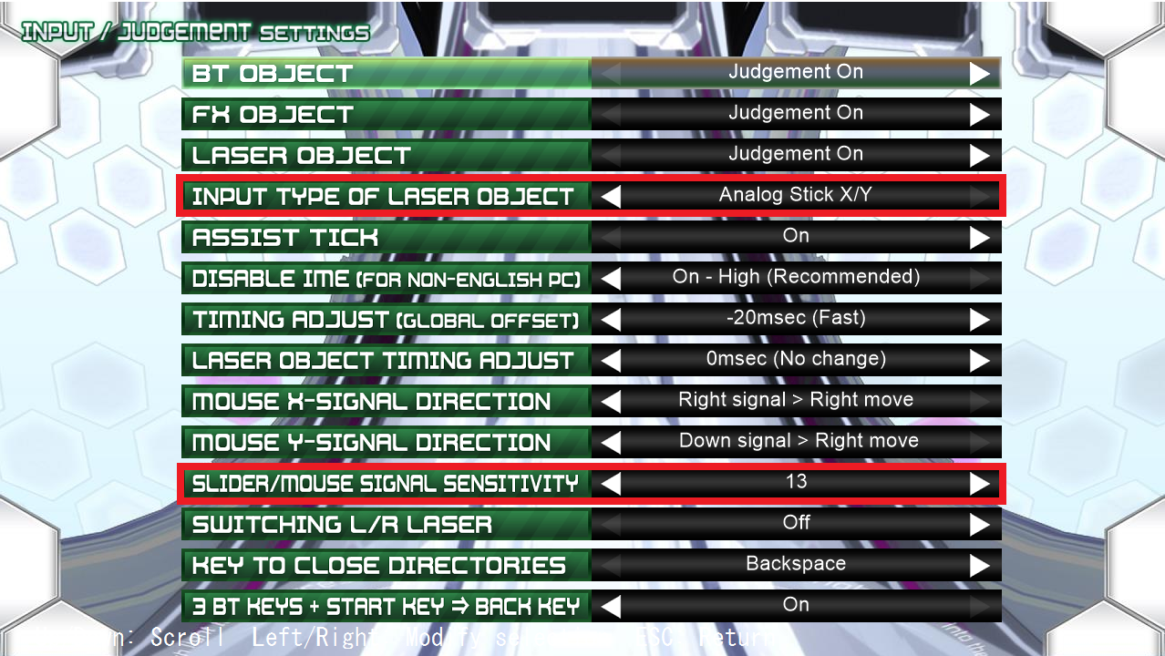
Set Input Type to Analog Stick X/Y and set Signal Sensitivity to a high value (>10)
Test KSM play: https://youtu.be/374v2gmAJd4
TODO: In-Program Documentation

