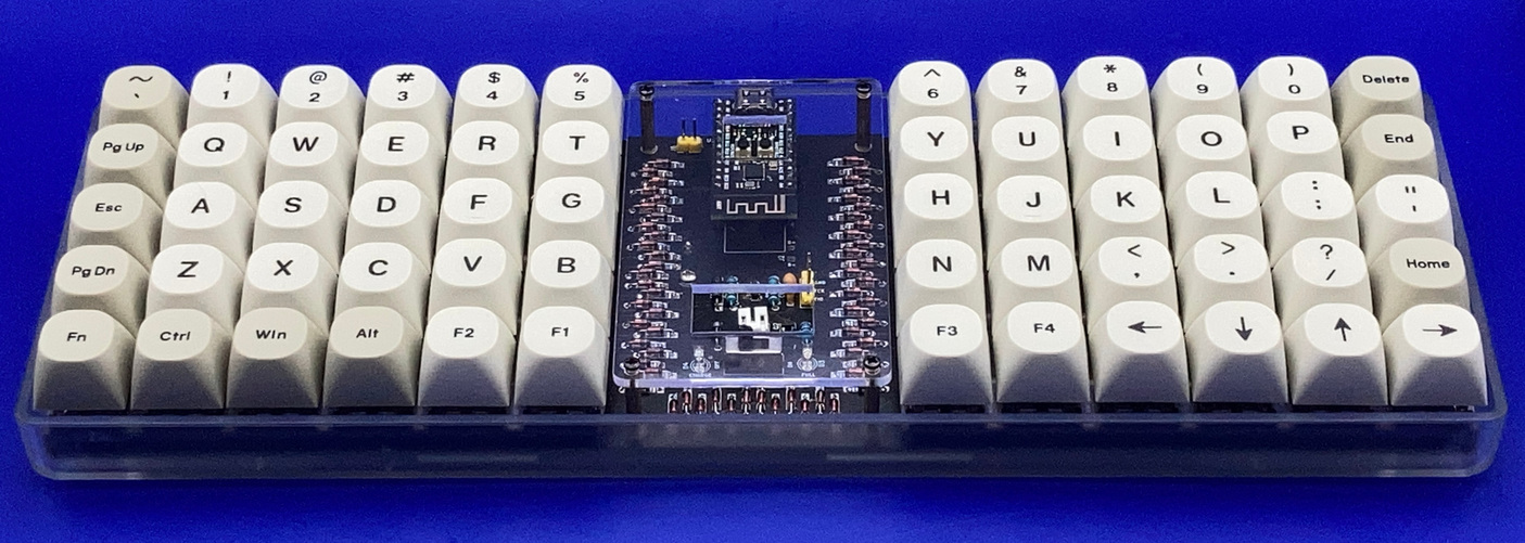
This document is a guide for soldering a build of the WABBLE-60 keyboard.
-
Components:
- 1x 1uF radial cerematic capactior
- 2x 2-pin PH2.0 JST right-angle male header
- 1x 12-pin or 16-pin USB-C Connector SMD
- 2x 5.1k resistor (1/4W through-hole, or 0805)
- 1x 22k resistor (1/4W through-hole, or 0805)
- 1x 10k resistor (1/4W through-hole, or 0805)
- 1x resistor (1/4W through-hole, or 0805) for R_PROG of TP4054
- 1x TP4054
- 1x BSS138
- 2x 1N5819 Schottky diode
- 1x 3mm LED (green)
- 1x 3mm LED (red)
- 1x SS-12F44 switch
- 1x 1x40 round-pins female headers, pitch 2.54 (for U1)
- for socketing the BLE core board
- 1x male headers, pitch 2.54 (for J5, J6)
- 60x 1N4148 diodes
- 60x MX-compatible switches
-
Additional Materials:
-
1x WeAct BLE Core Board
-
1x 1x40 round-pins male headers, pitch 2.54
- for socketing the BLE core board
-
GH-60 case
- Preferably one with enough room for a LiPo battery underneath the PCB.
-
1x LiPo battery
-
For mounting underneath the PCB, should be no thicker than 4mm for many GH-60 cases.
-
1x 2-pin PH2.0 JST female connector, if not soldering the battery directly to the board.
-
Heat-shrink tubing, if not soldering the battery directly to the board.
-
-
1x Pair of switch plates
- SVGs can be found in the WABBLE-60 rev2024.2 release
(or the source files under
cad/).
- SVGs can be found in the WABBLE-60 rev2024.2 release
(or the source files under
-
1x Cover plate for core board area
- SVGs can be found in the WABBLE-60 rev2024.2 release
(or the source files under
cad/).
- SVGs can be found in the WABBLE-60 rev2024.2 release
(or the source files under
-
3x M2 screws, for mounting the PCB to the GH-60 case
- Typically these come with the case.
-
4x sets of M2 spacers and screws, for mounting the cover plate
- 16mm FF spacer (if socketing the core board with round male and female pins)
-
It may also be useful to have:
-
Some way of reading UART output
- A spare dev board (like a Raspberry Pi Pico) can be used to read UART
- e.g. WeAct have a TTL to USB board
-
WCH-Link, for two-wire debugging the CH58x/CH59x core board
- WeAct Studio also offer a WCHLink board
- Solder a PH2.0 connector to the LiPo battery.
- Socket the WeAct BLE core board.
- Solder the USB connector.
- Solder the LiPo charging circuitry.
- Solder the switch diodes.
- Solder the tall through-hole components.
- Check the USB works, and the LiPo charging works.
- Solder the switches.
-
Solder a PH2.0 connector to the LiPo battery.
Alternatively, the battery can be soldered directly to the WABBLE-60 PCB.
-
Socket the WeAct BLE core board.
Rather than directly soldering the WeAct BLE core board to the WABBLE-60 PCB, I instead recommend socketing the core board.
By using round-pins, the core board can be easily inserted/removed from the WABBLE-60.
To do this, gather the WeAct BLE core board, round-pin male headers, and a spare breadboard.
Cut the header pins down to an appropriate number.
Solder the round-pin headers to the core board:
The pins can be cut, and the solder joints reflowed, which hopefully looks a bit neater than leaving the pins untrimmed:
-
Solder the USB connector.
Solder the USB connector to J1, and 2x 5.1k resistors to R1, R2:
It may be helpful to review a video on soldering a USB-C port.
-
Solder the LiPo charging circuitry.
Solder the TP4054 to U2:
Solder 2x 1N5819 to D1, D2; a 22k resistor to R3; a 10k resistor to R4; and the R_PROG resistor to R5:
Solder the BSS138 to Q1:
-
Solder the switch diodes.
It's convenient to solder the diodes for the keyboard switches before soldering the taller through-hole components.
Recall, the diode's mark indicates the cathode, which should be inserted closer to the square through-hole pad.
It may be too tedious to try to solder all 60 at once. One approach is to solder just the "inner" diodes at once, then the "outer" diodes.
-
Solder the tall through-hole components.
Now the remaining (tall) through-hole components can be soldered.
It should be fairly clear where each goes: a 1uF radial ceramic capacitor to C1; a SS-12F44 to SW1; 2x 2-pin PH2.0 right-angle headers in J3, J4; round-pin female headers for U1; male headers for J5, J6.
For the LEDs, recall the cathode is the shorter LED leg; the D3, D4 uses square pad for the cathode.
Also take care to not mix up the red and green LEDs, if you went with different colours for each.
For the PH2.0 headers, orientation needs to match the silkscreen markings.
-
Check the USB connector and LiPo charging.
Before soldering in the switches, it's a good idea to check the USB connector has been soldered correctly, and that the LiPo charging works.
For checking the USB, plugging a USB-C cable into J1 should behave the same as plugging into the core board's USB connector. e.g. you should be able to see the output when running
wchisp info.For checking the LiPo charging, you'll want to observe that the 'FULL' LED is bright when a USB cable is connected to the WABBLE-60 PCB (either to J1, or to the core board) and a full LiPo battery is connected; or that the 'CHARGE' LED is bright if the LiPo battery is not fully charged when a USB cable is connected.
-
Solder the switches.
With everything else soldered (& checked), solder the switches:
e.g. Insert the four corner switches into each switch plate half, ensuring that the switch plates are correctly oriented with the mounting holes at the PCB edges, and then insert the remaining switches into the switch plate. With the switches all inserted in the switch plate & mounted to the board, solder each of the switches.


