This is the Nuvoton NPCM750 evaluation board layer. The NPCM750 is an ARM based SoC with external DDR RAM and supports a large set of peripherals made by Nuvoton. More information about the NPCM7XX can be found here.
- Working with openbmc master branch
- Working with NTIL linux 4.19.16 for Poleg
This layer depends on:
  URI: [email protected]:Nuvoton-Israel/openbmc
  branch: master
Please submit any patches against the NPCM750 evaluation board layer to the maintainer of nuvoton:
- Oshri Alkoby, [email protected]
- Joseph Liu, [email protected]
- Medad CChien, [email protected]
- Tyrone Ting, [email protected]
- Stanley Chu, [email protected]
- Tim Lee, [email protected]
- Dependencies
- Contacts for Patches
- Features of NPCM750 Evaluation Board
- IPMI Comamnds Verified
- Image Size
- Modifications
This is a Virtual Network Computing (VNC) server programm using LibVNCServer.
- Support Video Capture and Differentiation(VCD), compares frame by hardware.
- Support Encoding Compression Engine(ECE), 16-bit hextile compression hardware encoding.
- Support USB HID, support Keyboard and Mouse.
The VNC viewer also enabled in webui with below patches.
- Implement KVM in webui using novnc module
- This patch is provided by Ed tanous.
- Remove sending sec-websocket-protocol in novnc module
Source URL
- https://github.com/Nuvoton-Israel/obmc-ikvm
- https://github.com/Nuvoton-Israel/openbmc/blob/master/meta-evb/meta-evb-nuvoton/meta-evb-npcm750/recipes-phosphor/interfaces/phosphor-rest/0001-add-kvm-handler.patch
How to use
- Prepare a motherboard with a PCI-E slot at least.
- Plug Poleg EVB into motherboard with PCI-E connection.
- Connect a micro usb cable from your workstation to J1 header of Poleg EVB.
- Connect an ethernet cable between your workstation and J12 header of Poleg EVB.
- Power up the Poleg EVB and motherboard.
- Noted the power on sequence to ensure the graphic of Poleg EVB is attached.
Poleg EVB -> motherboard
- Noted the power on sequence to ensure the graphic of Poleg EVB is attached.
- Make sure the network is connected with your workstation.
- Launch a browser in your workstation and you will see the entry page.
/* Web Server */ https://<poelg ip> - Login to OpenBMC home page
Username: root Password: 0penBmc - Navigate to noVNC viewer
Server control -> KVM
Performance
- Host OS: Windows Server 2012 R2
| Playing video: AQUAMAN | Real VNC viewer | noVNC viewer |
|---|---|---|
| Host Resolution | FPS | FPS |
| 1024x768 | 25 | 8 |
| 1280x1024 | 20 | 4 |
| 1600x1200 | 14 | 3 |
| Scrolling bar: Demo video | Real VNC viewer | noVNC viewer |
|---|---|---|
| Host Resolution | FPS | FPS |
| 1024x768 | 31 | 15 |
| 1280x1024 | 24 | 12 |
| 1600x1200 | 20 | 7 |
The preferred settings of RealVNC Viewer
Picture quality: Custom
ColorLevel: rgb565
PreferredEncoding: Hextile
Maintainer
- Joseph Liu
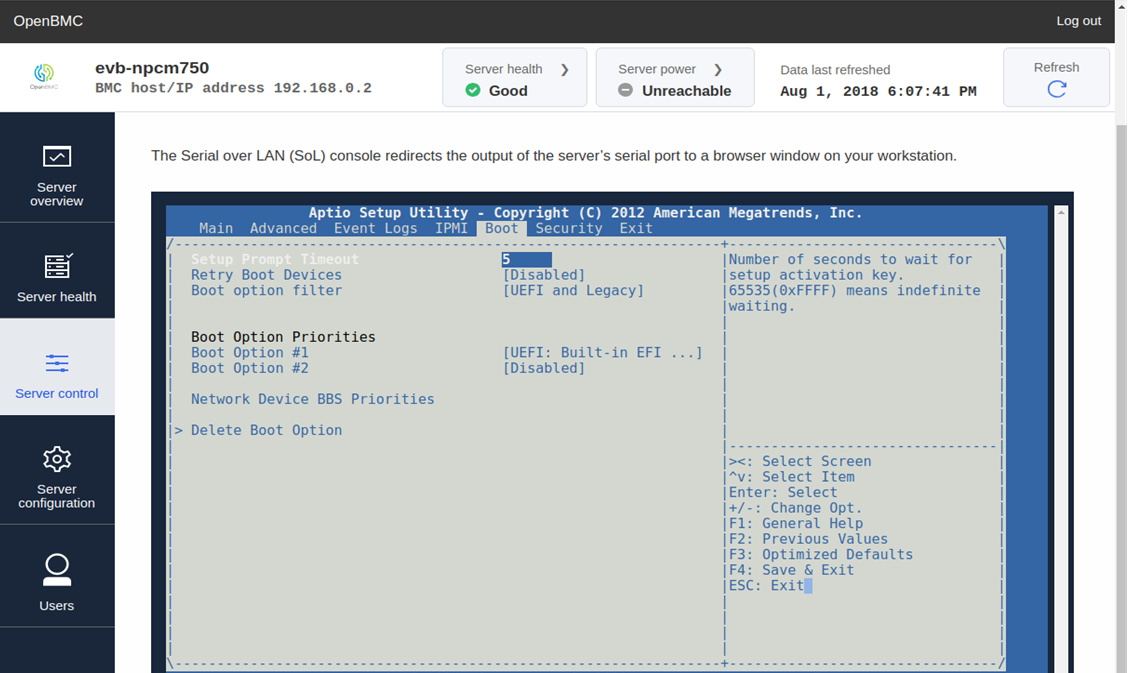
The Serial over LAN (SoL) console redirects the output of the server’s serial port to a browser window on your workstation.
This is a patch for enabling SOL in phosphor-webui on Nuvoton's NPCM750.
The patch provides the obmc-console configuration.
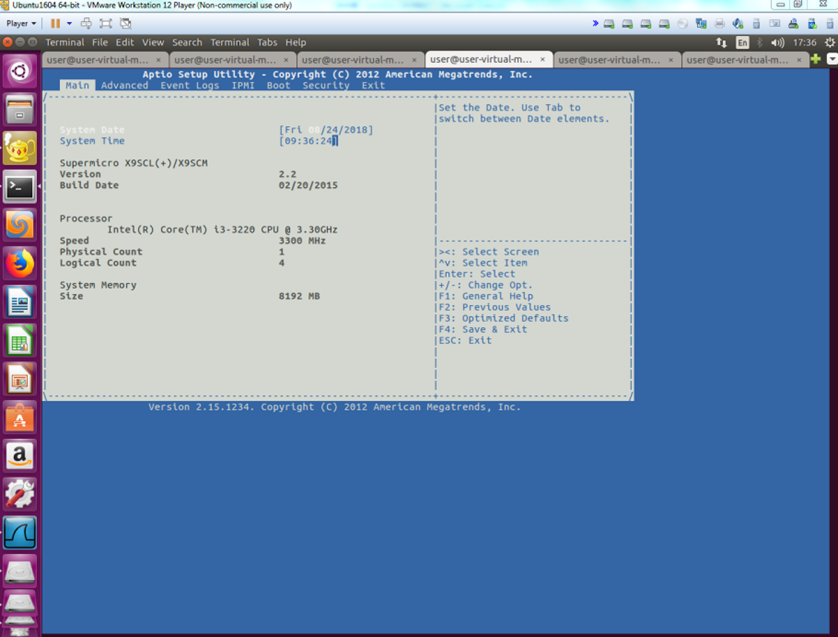
It's verified with Nuvoton's NPCM750 solution (which is referred as Poleg here) and Supermicro MBD-X9SCL-F-0.
Source URL
How to use
-
Prepare a Poleg EVB with up-to-date boot block, Uboot and OpenBMC versions with this SOL patch applied. Check with Nuvoton support for the most recent versions.
-
Prepare a Supermicro MBD-X9SCL-F-0 motherboard and a LPC cable.
The UEFI firmware version in Supermicro MBD-X9SCL-F-0 for verification is 2.15.1234.
-
Connect pins of the JTPM header on Supermicro MBD-X9SCL-F-0 to the J10 header on Poleg EVB with the LPC cable:
- Connect pin 1-3, 5, 7-8, 10-12, 15-17 of JTPM with corresponding pins of J10, one on one.
-
Steps to copy UEFI SOL related drivers to a USB drive.
- Format the USB drive in FAT or FAT32.
- Download PolegSerialDxe.efi and TerminalDxe.efi from https://github.com/Nuvoton-Israel/openbmc-uefi-util/tree/npcm7xx_v2.1/sol_binary and copy them to the USB drive.
-
Power up the Poleg EVB and steps to prepare a working terminal for Poleg:
- Download and install the USB-to-UART driver from: http://www.ftdichip.com/Drivers/VCP.htm according to the host OS in your workstation.
- Connect a micro usb cable from your workstation to J2 header of Poleg EVB.
- Wait for the FTDI driver to be installed automatically. The COM port number is assigned automatically.
- Open a terminal (e.g., Tera Term version 4.87) and set the correct COM port number assigned by the FTDI driver (in previous step).
- The COM port should be configured as follows: 115200, 8 bit, 1 stop-bit, no parity, no flow control.
- Press and release the PWR-ON-RST (SW3) button to issue a Power-On-reset. It's expected to see messages output by Poleg on the terminal. Use the following login name/password to login into Poleg.
- Login name: root
- Login password: 0penBmc
-
Steps to configure Supermicro MBD-X9SCL-F-0 UEFI setting for SOL:
-
Do not plug any bootable device into Supermicro MBD-X9SCL-F-0.
-
Power up Supermicro MBD-X9SCL-F-0 and boot into UEFI setting.
-
Navigate to
Super IO ConcifugrationinAdvancedmenu option and enter intoSuper IO Concifugration. -
Configure serial port 1 to IO=3E8h; IRQ=5, and then disable it.
-
Go back to the main UEFI setting.
-
Navigate to
Bootmenu option and selectUEFI: Built-in EFI Shellas Boot Option #1.- Make sure that the rest boot options are set to Disabled.
-
Navigate to
Exitmenu option and selectSave changes and Reset. -
Press
Yesin the prompt window and it will reboot then. -
Wait for Supermicro MBD-X9SCL-F-0 to boot into UEFI shell.
-
Plug the USB drive prepared in step-4 into Supermicro MBD-X9SCL-F-0's usb slot.
-
Input the following command at UEFI shell prompt, press enter key and it will route to UEFI shell again.
exit -
Check the device mapping table of the USB drive in UEFI shell. It is fs0: here for example.
-
Input the following command at UEFI shell prompt, press enter key and the prompt will show fs0:> from now.
fs0: -
Input the following command at UEFI shell prompt and press the enter key.
load PolegSerialDxe.efi -
Input the following command at UEFI shell prompt and press the enter key.
load TerminalDxe.efi -
Unplug the usb drive.
-
Input the following command at UEFI shell prompt, press the enter key and it will route to the UEFI setting.
exit
-
-
Configure the ethernet communication between your workstation and Poleg EVB:
- Connect an ethernet cable between your workstation and J7 header of Poleg EVB.
- Configure your workstation's ip address to 192.168.0.1 and the netmask to 255.255.255.0 as an example here.
- Configure Poleg EVB ip address to 192.168.0.2 and the netmask to 255.255.255.0. For example, input the following command in the terminal connected to Poleg EVB on your workstation and press enter key.
ifconfig eth0 192.168.0.2 netmask 255.255.255.0
-
Run SOL:
- Please disable the proxy setting for this test if it's configured.
- Launch a browser in your workstation and navigate to https://192.168.0.2.
- Bypass the secure warning and continue to the website.
- Enter the BMC Username and Password (defaults: root/0penBmc).
- You will see the OpenBMC management screen.
- Click
Server controlat the left side of the OpenBMC management screen. - A
Serial over LAN consolemenu item prompts then and click it. - A specific area will display the UEFI setting of Supermicro MBD-X9SCL-F-0.
- (Optional) If the area doesn't display the UEFI setting clearly, use the mouse pointer to click in the area and press the Esc key.
- It shows a prompt window named
Exit Without Saving, chooseNoand press enter key to refresh the area for showing UEFI setting entirely.
- It shows a prompt window named
- Please enable the proxy setting if it's just disabled for the test.
Maintainer
- Tyrone Ting
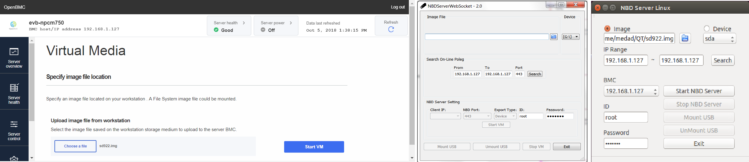
Virtual Media (VM) is to emulate an USB drive on remote host PC via Network Block Device(NBD) and Mass Storage(MSTG).
Source URL
- https://github.com/Nuvoton-Israel/openbmc/tree/master/meta-evb/meta-evb-nuvoton/meta-evb-npcm750/recipes-support/nbd
- https://github.com/Nuvoton-Israel/openbmc/blob/master/meta-evb/meta-evb-nuvoton/meta-evb-npcm750/recipes-kernel/linux/linux-nuvoton/0002-nbd-fix-reconnect.patch
- https://github.com/Nuvoton-Israel/openbmc/blob/master/meta-evb/meta-evb-nuvoton/meta-evb-npcm750/recipes-phosphor/interfaces/phosphor-rest/0002-add-vm-handler.patch
- https://github.com/Nuvoton-Israel/openbmc/blob/master/meta-evb/meta-evb-nuvoton/meta-evb-npcm750/recipes-phosphor/webui/phosphor-webui/0002-Implement-VM-in-webui.patch
How to use
-
Clone a physical usb drive to an image file
NOTICE : You can skip this step, if you enable VM via APP.
-
For Linux - use tool like dd
dd if=/dev/sda of=usb.img bs=1M count=100bs here is block size and count is block count.
For example, if the size of your usb drive is 1GB, then you could set "bs=1M" and "count=1024"
-
For Windows - use tool like Win32DiskImager.exe
NOTICE : A simple *.iso file cannot work for this.
-
-
Enable Virtual Media
2.1 VM-WEB
- Login to BMC and switch to webpage of VM on your browser
https://XXX.XXX.XXX.XXX/#/server-control/vm - Operations
- After
Chose an Image File, clickStart VMto start VM network service (still not hook USB disk to host platform) - After
Start VM, clickMount USBto hook the emulated usb disk to host platform, or clickStop VMto stop VM network service. - After
Mount USB, clickUnMount USBto emulate unplugging the usb disk from host platform - After
UnMount USB, clickStop VMto stop VM network service, or clickMount USBto hook USB disk to host platform.
- After
2.2 VM-APP
-
Launch windows/linux application
NOTICE : use
sudoto launch app in linux and installnmapfirst -
Operations
- After
Chose an Image FileorSelect an USB Drive, clickSearchto check which BMCs are on line - Select any on line BMC and key in
Account/Passwordand clickStart VMto start VM network service (still not hook USB disk to host platform) - After
Start VM, clickMount USBto hook the emulated usb disk to host platform, or clickStop VMto stop VM network service. - After
Mount USB, clickUnMount USBto emulate unplugging the usb disk from host platform - After
UnMount USB, clickStop VMto stop VM network service, or clickMount USBto hook USB disk to host platform.
- After
- Login to BMC and switch to webpage of VM on your browser
Performance
-
APP stands for QT application runs on windows/linux
-
Web stands for JavaScript NBD Server runs on browser
-
Support functions
Image Source\OP Read Write USB Drive APP only APP only Image APP/Web APP only -
Speed
Server\OP Read Write APP 512KB/s 2MB/s Web 512KB/s NULL Note: Every read request should get data from NBD Server via network, but each write request just pass data to filesystem, and filesystem will deals with passing data to NBD Server, so read takes more time than write.
Maintainer
- Medad CChien
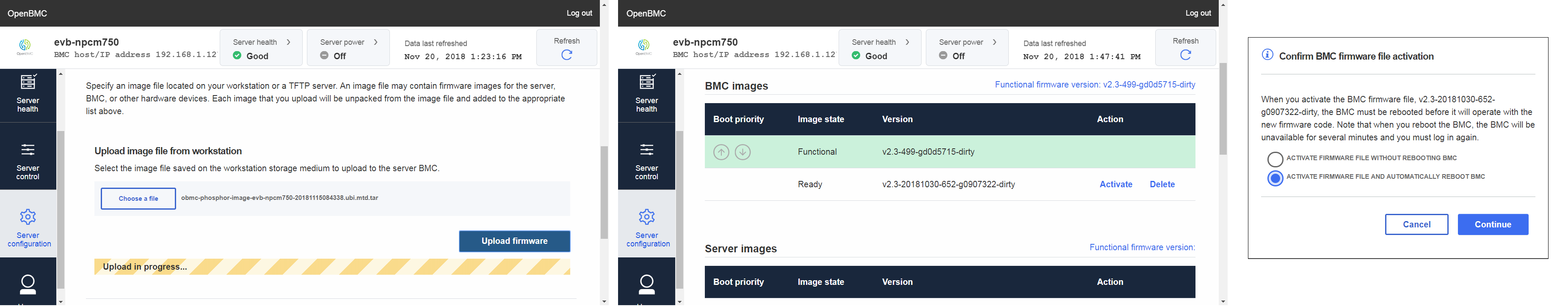
This is a secure flash update mechanism to update BMC firmware via WebUI.
Source URL
How to use
-
Upload update package from webui, then you will see
Activateif you select activate, then you will see activation dialog at item 2
DeleteIf you select delete, then the package will be deleted right now
-
Confirm BMC firmware file activation
ACTIVATE FIRMWARE FILE WITHOUT REBOOTING BMCif you select this, you need to reboot BMC manually, and shutdown application will run update script to flash image into spi flash
ACTIVATE FIRMWARE FILE AND AUTOMATICALLY REBOOT BMCif you select this, BMC will shutdown right now, and shutdown application will run update script to flash image into spi flash
Maintainer
- Medad CChien
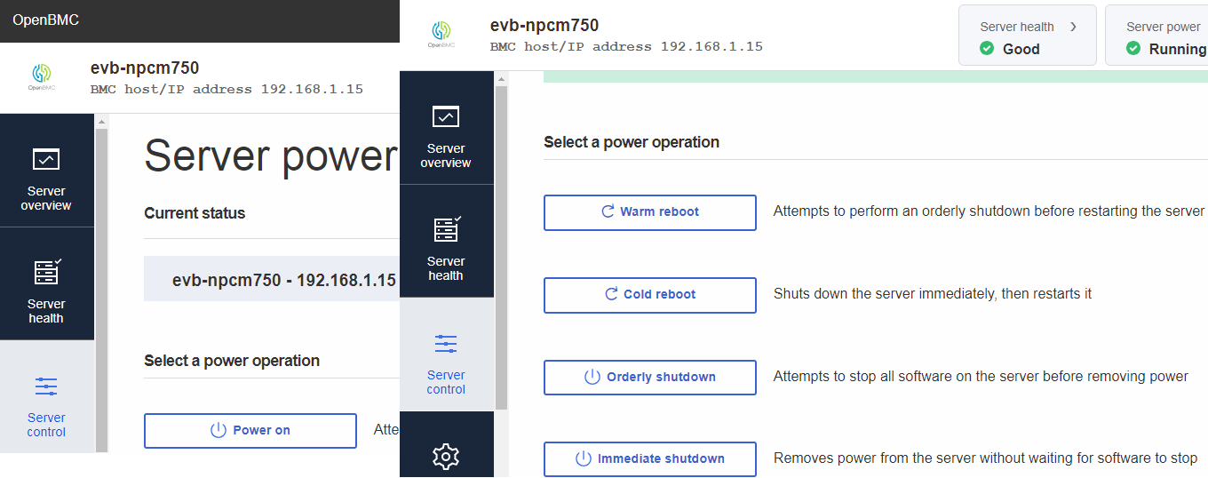
Server Power Operations are using to Power on/Warm reboot/Cold reboot/Orderly shutdown/Immediate shutdown remote host PC.
Source URL
How to use
-
Connect pins of the PWRON header on generic motherboard to the J13 header on Poleg EVB
-
Depending on your motherboard, you need to find PWRON header and connect to pin5-6 of J13 header on Poleg EVB.
You can check the schematic of Poleg EVB about J13 that pin5-6 for POWER_SW and pin3-4 for RESET_SW. However, according to
Server power operationsdesign on WebUI that only use POWER_SW pin forWarm reboot,Cold reboot,Orderly shutdownandImmediate shutdownfunction implementation. Thus, we didn't need to use RESET_SW pin for those power operations on WebUI.
-
-
Configure reaction of power button on generic motherboard's OS
-
When motherboard's OS is running Linux and you press PWRON header on motherboard, you're prompted with a list of options - this is the interactive shutdown. The OS will go Orderly shutdown for a while if you didn't select any action from it. If you don't want this interactive shutdown pop up and hope OS go Orderly shutdown directly, you can enter below command in terminal before testing:
gsettings set org.gnome.settings-daemon.plugins.power button-power 'shutdown' -
When motherboard's OS is running Windows and you press PWRON header on motherboard, the default reaction is Orderly shutdown. Thus, you didn't need to configure reaction of power button in Windows. But, if you find the default reaction is not Orderly shutdown, please check
Control Panel->Power Options->System Settingsin Windows OS. -
About Watchdog patch
There is a package phosphor-watchdog included in OpenBMC now. The watchdog daemon is started on host's power on, which is used to monitor if host is alive. In normal case, when host starts, it will send IPMI commands to kick watchdog and so everything would work fine. If host fails to start, the watchdog eventually timeout. However, the default watchdog timeout action is HardReset which is defined at Watchdog.interface.yaml in phosphor-dbus-interfaces that will cause host rebooted after power on.
Currently, we just use Poleg EVB with generic motherboard that has some limitations, thus when we use Ubuntu or Windows as host OS, we didn't receive watchdog off IPMI commands sent from OS or BIOS side, so the default watchdog timeout action will be triggered and host will be rebooted after we pressed
Power onbutton fromServer control->Server power operationsof WebUI, and that is unexpected behavior. However, we've provided a patch to makePower onfunction work normally for demo purpose, if your host will send watchdog off IPMI command normally then you can remove this patch 0001-Set-Watchdog-ExpireAction-as-None.patch from phosphor-dbus-interfaces_%.bbappend.
-
-
Configure GPIO pin definitions for POWER_SW, RESET_SW and PGOOD on Poleg EVB
-
Pin POWER_SW (GPIO219) is use to do all server power operations, pin RESET_SW (GPIO218) is reserve for reset operations, and PGOOD (GPIO126) is use to monitor DC real status that indicate
Server powerin WebUI. -
If other GPIO pins are preferred, please modify the file gpio_defs.json .
-
Content below is a part of gpio_defs.json for this sample:
"power_config": {
    "power_good_in": "PGOOD",
    "power_up_outs": [
        {"name": "POWER_UP_PIN", "polarity": false}
    ],
    "reset_outs": [
        {"name": "RESET_UP_PIN", "polarity": false}
    ]
}

"name": "PGOOD",
"num": 126,
"direction": "in"

"name": "RESET_UP_PIN",
"num": 218,
"direction": "out"

"name": "POWER_UP_PIN",
"num": 219,
"direction": "out"
"name" here is referred in code and fixed, please don't modify it. "num" means GPIO pin number and changeable here, "direction" should be set as "in" for PGOOD, "out" for RESET_UP_PIN and POWER_UP_PIN, and "polarity" should be set as "false" for RESET_UP_PIN and POWER_UP_PIN accordind Poleg EVB schematic.
-
-
Server Power on
-
Press
Power onbutton fromServer control->Server power operationsof WebUI.[email protected] is the one driving the boot of the system.
-
-
Server Power off (Soft)
-
Press
Orderly shutdownbutton fromServer control->Server power operationsof WebUI.The soft server power off function is encapsulated in the [email protected] that is soft in that it notifies the host of the power off request and gives it a certain amount of time to shut itself down.
-
-
Server Power off (Hard)
-
Press
Immediate shutdownbutton fromServer control->Server power operationsof WebUI.The hard server power off is encapsulated in the [email protected] that will force the stopping of the soft power off service if running, and immediately cut power to the system.
-
-
Server Reboot (Warm)
-
Press
Warm rebootbutton fromServer control->Server power operationsof WebUI.The warm reboot of the server is encapsulated in the [email protected] that will utilize the server power off (soft) target [email protected] and then, once that completes, start the host power on target [email protected].
-
-
Server Reboot (Cold)
-
Press
Cold rebootbutton fromServer control->Server power operationsof WebUI.The cold reboot of the server is shutdown server immediately, then restarts it. This target will utilize the Immediate shutdown target [email protected] and then, start the host power on target [email protected].
-
Maintainer
- Tim Lee
Chassis Buttons POWER/RESET/ID can be used to power on/off, reset host server and identify this server to IT people's management console.
Source URL
How to use
-
Connect pins of the PWRON header on generic motherboard to the J13 header on Poleg EVB.
- Depending on your motherboard, you need to find PWRON header and connect to pin5-6 of J13 header on Poleg EVB.
You can check the schematic of Poleg EVB about J13 that pin5-6 for POWER_SW.
- Depending on your motherboard, you need to find PWRON header and connect to pin5-6 of J13 header on Poleg EVB.
-
Prepare 3 buttons with sensing pins pulled high when not pressed, and sensed low level when pressed. Connect sensing pins of them with the J23 GPIOs header of Poleg EVB, one on one.
-
Power button
Connect Power button sensing pin to pin1 of header J23 of Poleg EVB.
-
Reset button
Connect Reset button sensing pin to pin2 of header J23 of Poleg EVB.
-
ID button
Connect ID button sensing pin to pin3 of header J23 of Poleg EVB.
-
Alternative GPIO pins for buttons
On header J23 of Poleg EVB are 10 available GPIO pins available for customer application. Here, GPIO120 (pin1) is use to sense Power button, GPIO122 (pin2) is use to sense Reset button, and GPIO124 (pin3) is use to sense ID button.
If other GPIO pins are preferred, please modify the file gpio_defs.json , and connect corresponding pins of header J23 of Poleg EVB to button sensing pins, respectively.
Content below is a part of gpio_defs.json for this sample:
"name": "POWER_BUTTON",
"num": 120,
"direction": "both"

"name": "RESET_BUTTON",
"num": 122,
"direction": "both"

"name": "ID_BTN",
"num": 124,
"direction": "both"
"name" here is referred in code and fixed, please don't modify it. "num" means GPIO pin number and changeable here, "direction" should be set as "both" here because these pins will serve as input pins, with both rising and falling edge interrupt enabled.
-
Maintainer
- Tim Lee
-
SNTP
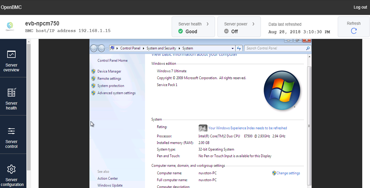
Network Time Protocol (NTP) is a networking protocol for clock synchronization between computer systems over packet-switched, variable-latency data networks.systemd-timesyncd is a daemon that has been added for synchronizing the system clock across the network. It implements an SNTP (Simple NTP) client. This daemon runs with minimal privileges, and has been hooked up with systemd-networkd to only operate when network connectivity is available.
The modification time of the file /var/lib/systemd/timesync/clock indicates the timestamp of the last successful synchronization (or at least the systemd build date, in case synchronization was not possible).
Source URL
How to use
-
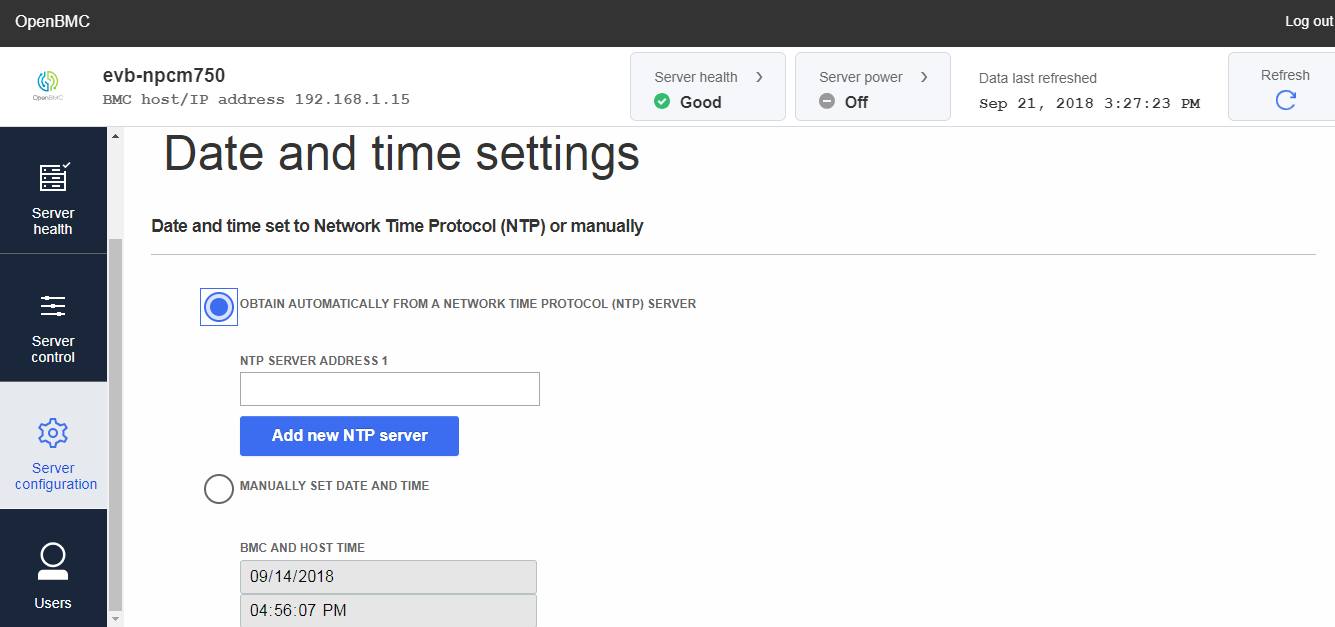
Enable NTP by Web-UI
Server configuration
->Date and time settings -
Enable NTP by command
timedatectl set-ntp truetimedatectl result will show systemd-timesyncd.service active: yes
If NTP is Enabled and network is Connected (Using eth2 connect to router), we will see the item systemd-timesyncd.service active is yes and System clock synchronized is yes. Thus, system time will sync from NTP server to get current time.
-
Get NTP status
timedatectlLocal time: Mon 2018-08-27 09:24:51 UTC
Universal time: Mon 2018-08-27 09:24:51 UTC
RTC time: n/a
Time zone: n/a (UTC, +0000)
System clock synchronized: yes
systemd-timesyncd.service active: yes
RTC in local TZ: no -
Disable NTP
timedatectl set-ntp falsetimedatectl result will show systemd-timesyncd.service active: no
-
Using Local NTP server Configuration
When starting, systemd-timesyncd will read the configuration file from /etc/systemd/timesyncd.conf, which looks like as below:[Time]
#NTP=
#FallbackNTP=time1.google.com time2.google.com time3.google.com time4.google.comBy default, systemd-timesyncd uses the Google Public NTP servers time[1-4].google.com, if no other NTP configuration is available. To add time servers or change the provided ones, uncomment the relevant line and list their host name or IP separated by a space. For example, we setup NB windows 10 system as NTP server with IP 192.168.1.128
[Time]
NTP=192.168.1.128
#FallbackNTP=time1.google.com time2.google.com time3.google.com time4.google.com -
Poleg connect to local NTP server of windows 10 system
Connect to NB through eth0 EMAC interface, and set static IP 192.168.1.15ifconfig eth0 up ifconfig eth0 192.168.1.15Note: Before that you need to setup your NTP server (192.168.1.128) on Windows 10 system first
Modify /etc/systemd/timesyncd.conf file on Poleg as we mentioned
[Time]
NTP=192.168.1.128Re-start NTP to make effect about our configuration change
systemctl restart systemd-timesyncd.serviceCheck status of NTP that show already synced to our local time server
systemctl status systemd-timesyncd.service -l --no-pagerStatus: "Synchronized to time server 192.168.1.128:123 (192.168.1.128)."
Verify Web-UI
Server overview->BMC timewhether sync from NTP server as same as timedatectl. (Note: timedatectl time zone default is UTC, thus you will find the BMC time is UTC+8)timedatectlLocal time: Thu 2018-09-06 07:24:16 UTC
Universal time: Thu 2018-09-06 07:24:16 UTC
RTC time: n/a
Time zone: n/a (UTC, +0000)
System clock synchronized: yes
systemd-timesyncd.service active: yes
RTC in local TZ: no
-
-
Time settings
Phosphor-time-manager provides two objects on D-Bus_/xyz/openbmc_project/time/bmc
/xyz/openbmc_project/time/host_
BMC time is used by journal event log record, and Host time is used by Host do IPMI Set SEL Time command to sync BMC time from Host mechanism in an era of BMC without any network interface.
Currently, we cannot set Host time no matter what we use busctl, REST API or ipmitool set time set command. Due to phosphor-settingd this daemon set default TimeOwner is BMC and TimeSyncMethod is NTP. Thus, when TimeOwner is BMC that is not allow to set Host time anyway.A summary of which cases the time can be set on BMC or HOST
Mode Owner Set BMC Time Set Host Time NTP BMC Fail to set Not allowed (Default setting) NTP HOST Not allowed Not allowed NTP SPLIT Fail to set OK NTP BOTH Fail to set Not allowed MANUAL BMC OK Not allowed MANUAL HOST Not allowed OK MANUAL SPLIT OK OK MANUAL BOTH OK OK If user would like to set Host time that need to set Owner to SPLIT in NTP mode or set Owner to HOST/SPLIT/BOTH in MANUAL mode. However, change Host time will not effect BMC time and journal event log timestamp.
Set Time Owner to Split
### With busctl on BMC
busctl set-property xyz.openbmc_project.Settings \
   /xyz/openbmc_project/time/owner xyz.openbmc_project.Time.Owner \
   TimeOwner s xyz.openbmc_project.Time.Owner.Owners.Split

### With REST API on remote host
curl -c cjar -b cjar -k -H "Content-Type: application/json" -X  PUT  -d \
   '{"data": "xyz.openbmc_project.Time.Owner.Owners.Split" }' \
   https://${BMC_IP}/xyz/openbmc_project/time/owner/attr/TimeOwner
TimeZone
According OpenBMC current design that only support UTC TimeZone now, we can use below command to get current support TimeZone on Polegtimedatectl list-timezonesMaintainer
-
Tim Lee

phosphor-hwmon daemon will periodically check the sensor reading to see if it exceeds lower bound or upper bound . If alarm condition is hit and event generating option is on, it calls phosphor-logging API to generate a Log entry.
Later on, ipmi tool on host side can send IPMI command to BMC to get SEL events, phosphor-host-ipmid will convert the Log entries to SEL record format and reply to host.
Source URL
- https://github.com/Nuvoton-Israel/openbmc/tree/master/meta-evb/meta-evb-nuvoton/meta-evb-npcm750/recipes-phosphor/dbus
- https://github.com/Nuvoton-Israel/openbmc/tree/master/meta-evb/meta-evb-nuvoton/meta-evb-npcm750/recipes-phosphor/ipmi
- https://github.com/Nuvoton-Israel/openbmc/tree/master/meta-evb/meta-evb-nuvoton/meta-evb-npcm750/recipes-phosphor/sensors
How to use
-
Configure sensor and event generator
-
Add Inventory of Sensors
Inventory of Sensors is a map table that defines all types of SEL event BMC can generate. It is constructed from a yaml file, recipes-phosphor/ipmi/phosphor-ipmi-inventory-sel/config.yaml
Below is a sample config.yaml for Poleg EVB:
/xyz/openbmc_project/inventory/system:
  sensorID: 0x01
  sensorType: 0x12
  eventReadingType: 0x6F
  offset: 0x02
/xyz/openbmc_project/sensors/temperature/temp1/critical_high:
  sensorID: 0x02
  sensorType: 0x01
  eventReadingType: 0x01
  offset: 0x09
/xyz/openbmc_project/sensors/temperature/temp1/critical_low:
  sensorID: 0x02
  sensorType: 0x01
  eventReadingType: 0x01
  offset: 0x02
/xyz/openbmc_project/sensors/temperature/temp2/critical_high:
  sensorID: 0x03
  sensorType: 0x01
  eventReadingType: 0x01
  offset: 0x09
/xyz/openbmc_project/sensors/temperature/temp2/critical_low:
  sensorID: 0x03
  sensorType: 0x01
  eventReadingType: 0x01
  offset: 0x02
Please refer to Sensor and Event Code Tables in IPMI 2.0 spec for definition of sensorID, sensorType, eventReadingType, and offset
It defines 4 events which could be generated by 2 temperature sensors on Poleg EVB :
Name SensorID SensorType EventType Event Description temp1 2 Temperature Threshold Upper Critical - going high temp1 2 Temperature Threshold Lower Critical - going low temp2 3 Temperature Threshold Upper Critical - going high temp2 3 Temperature Threshold Lower Critical - going low -
Add Sensor Configuration File
Each sensor has a config file that defines the sensor name and its warning or critical thresholds. These files are located under recipes-phosphor/sensors/phosphor-hwmon%/obmc/hwmon/apb/.
Below is config for a LM75 sensor on Poleg EVB. The sensor type is temperature and its name is temp2. It has warning thresholds for upper and lower bound. The event generating option is also enabled for WARNHI and WARNLO threshold that forcing the sensor alarm to be recorded in a D-Bus object.
LABEL_temp1=temp2 WARNLO_temp1=28500 WARNHI_temp1=31000 EVENT_temp1=WARNHI,WARNLO -
Modify D-Bus Sensor Error Metadata interface
Modify the file Threshold.metadata.yaml to determine how to format the meta data of event records, like below :
- name: CriticalHigh
   level: ERR
   meta:
     - str: "SENSOR_DATA=%s"
       type: string
   inherits:
     - xyz.openbmc_project.Common.Callout.Inventory
- name: CriticalLow
  level: ERR
  meta:
    - str: "SENSOR_DATA=%s"
      type: string
  inherits:
    - xyz.openbmc_project.Common.Callout.Inventory
xyz.openbmc_project.Common.Callout.Inventory is inherited here in order to include CALLOUT_INVENTORY_PATH into phosphor-logging Log entry.
-
-
Dump events
-
Using WebUI
In
Event logpage of WebUI, the event may contain a related item like below.-
CALLOUT_INVENTORY_PATH means it has association info in Inventory of Sensors table and /xyz/openbmc_project/sensors/temperature/temp2/critical_high is the key to this map table.
-
SENSOR_DATA is the sensor reading while the event is recorded.
CALLOUT_INVENTORY_PATH=/xyz/openbmc_project/sensors/temperature/temp2/critical_high SENSOR_DATA=31000 _PID=2531
-
-
Using IPMI
Use IPMI utilities like ipmitool to send command for getting SEL records.
$ sudo ipmitool sel list

   1 | 10/04/2018 | 07:08:54 | Temperature #0x03 | Lower Critical going low  | Asserted
   2 | 10/04/2018 | 07:10:39 | Temperature #0x03 | Lower Critical going low  | Asserted
   3 | 10/04/2018 | 07:28:04 | Temperature #0x03 | Upper Critical going high | Asserted
   4 | 10/04/2018 | 07:28:11 | Temperature #0x03 | Upper Critical going high | Asserted
   5 | 10/04/2018 | 07:28:13 | Temperature #0x03 | Upper Critical going high | Asserted
   6 | 10/04/2018 | 07:46:34 | Temperature #0x03 | Upper Critical going high | Asserted
   7 | 10/04/2018 | 07:46:38 | Temperature #0x03 | Upper Critical going high | Asserted
   8 | 10/04/2018 | 07:46:43 | Temperature #0x03 | Upper Critical going high | Asserted
   9 | 10/04/2018 | 07:46:59 | Temperature #0x03 | Upper Critical going high | Asserted
   a | 10/04/2018 | 07:47:24 | Temperature #0x03 | Upper Critical going high | Asserted
   b | 10/04/2018 | 07:47:29 | Temperature #0x03 | Upper Critical going high | Asserted
   c | 10/04/2018 | 07:47:42 | Temperature #0x03 | Upper Critical going high | Asserted
   d | 10/04/2018 | 07:48:37 | Temperature #0x03 | Upper Critical going high | Asserted
   e | 10/04/2018 | 07:48:39 | Temperature #0x03 | Upper Critical going high | Asserted
   f | 10/04/2018 | 07:48:53 | Temperature #0x03 | Upper Critical going high | Asserted
  10 | 10/04/2018 | 09:19:11 | Temperature #0x03 | Lower Critical going low  | Asserted
  11 | 10/04/2018 | 09:20:22 | Temperature #0x03 | Lower Critical going low  | Asserted
  12 | 10/04/2018 | 09:20:24 | Temperature #0x03 | Lower Critical going low  | Asserted
  13 | 10/04/2018 | 09:33:24 | Temperature #0x03 | Upper Critical going high | Asserted
  14 | 10/04/2018 | 09:33:31 | Temperature #0x03 | Upper Critical going high | Asserted
-
Maintainer
- Stanley Chu
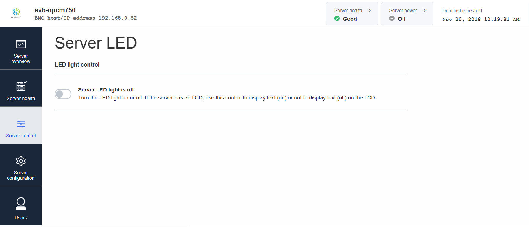
Turning on ServerLED will make hearbeat and identify leds on EVB start blinking
Source URL
How to use
-
Add enclosure_identify in LED config file
enclosure_identify: heartbeat: Action: 'Blink' DutyOn: 50 Period: 1000 identify: Action: 'Blink' DutyOn: 50 Period: 1000 -
Modify BSP layer config to select npcm750 LED config file
PREFERRED_PROVIDER_virtual/phosphor-led-manager-config-native = "npcm750-led-manager-config-native"
Maintainer
- Oshri Alkoby
- Stanley Chu
Source URL
How to use
-
Add ADC configuration file([email protected])
LABEL_in1 = "adc1"
LABEL_in2 = "adc2"
LABEL_in3 = "adc3"
LABEL_in4 = "adc4"
LABEL_in5 = "adc5"
LABEL_in6 = "adc6"
LABEL_in7 = "adc7"
LABEL_in8 = "adc8"
NOTE: For the LABEL assignment like LABEL_$(key) =
$(value), the $ (key) must have corresponding hwmon sysfs file in /sys/class/hwmon/hwmonN/$(key)_input -
Add configuration file to rootfs, modify phosphor-hwmon_%.bbappend
FENVS = "obmc/hwmon/ahb/apb/{0}" ADC_ITEMS = "[email protected]" SYSTEMD_ENVIRONMENT_FILE_${PN} += "${@compose_list(d, 'FENVS', 'ADC_ITEMS')}" -
output 1.15v to ADC channel3 input in Poleg EVB(pin 1 of J25)
-
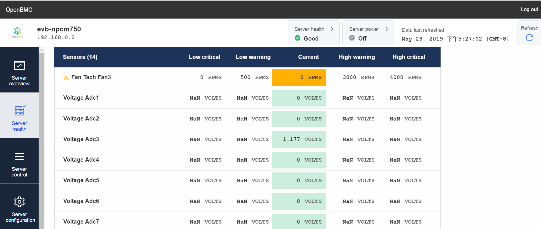
check ADC3 Voltage value in Web Sensors page
This value should be closed to 1.15
Maintainer
- Stanley Chu
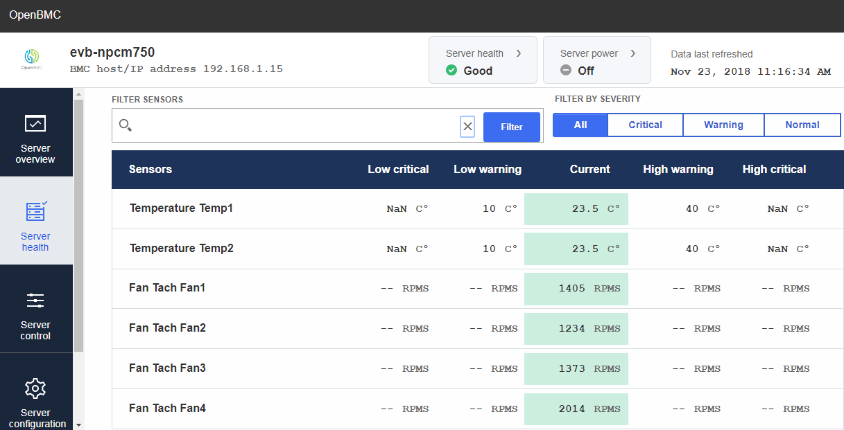
In Poleg, we support four FAN slots and FAN RPMS will dynamic adjustment according temperature variation. However, before using FAN function, you need to provide 12V external power into FLOPPY PWR on Poleg, 12V connect to PIN 4 and GND connect to PIN 2 of FLOPPY PWR.
Source URL
Default Web-UI only show one Fan Tach Fan1, and Poleg support four Fan Tach. Thus, we modify this file to support four Fan Tach.
-
How to use
-
Monitor FAN RPMS by Web-UI
Server health
->Sensors -
Enable FAN dynamic adjustment with temperature variation by command
systemctl start [email protected]This command will trigger systemd to execute chassis poweron target this unit. Due to FAN control function related to Host control, if you didn't connect to Host with your Poleg EVB, you can use this command to slmulate FAN control function.
-
Test FAN RPMS by command
echo 25 > /sys/class/hwmon/hwmon2/pwm1
echo 50 > /sys/class/hwmon/hwmon2/pwm2
echo 100 > /sys/class/hwmon/hwmon2/pwm3
echo 255 > /sys/class/hwmon/hwmon2/pwm6
We can set pwm value (0-255) for pwm1-3, and 6 to control FAN1-4 RPMS value by echo command and the result will show on Web-UI
-
Maintainer
- Oshri Alkoby
- Tim Lee
In Poleg, we support a FIFO for monitoring BIOS POST Code. Typically, this feature is used by the BMC to "watch" host boot progress via port 0x80 writes made by the BIOS during the boot process.
Source URL
This is a patch for enabling BIOS POST Code feature in phosphor-host-postd on Nuvoton's NPCM750. It's verified with Nuvoton's NPCM750 solution (which is referred as Poleg here) and Supermicro MBD-X9SCL-F-0.
-
How to use
-
Prepare a Poleg EVB with up-to-date boot block, Uboot and OpenBMC versions with this BIOS POST Code patch applied. Check with Nuvoton support for the most recent versions.
-
Prepare a Supermicro MBD-X9SCL-F-0 motherboard and a LPC cable.
-
Connect pins of the JTPM header on Supermicro MBD-X9SCL-F-0 to the J10 header on Poleg EVB with the LPC cable:
Connect pin 1-3, 5, 7-8, 10-12, 15-17 of JTPM with corresponding pins of J10, one on one.
-
Execute BIOS POST Code test program by command in Poleg
snooperThis command will trigger snooper test program to record BIOS POST Code from port 0x80 of host and save to file with timestamp filename in Poleg for each host power on or reset.
Saved filename format example: 2019_4_30_11_52_35_ON
-
Server Power on
Press
Power onbutton fromServer control->Server power operationsof WebUI.
During server power on, snooper test program will print received BIOS POST Code on screen and record to file in Poleg at the same time.Snooper test program print received BIOS POST Code example:
recv: 0x3
recv: 0x2
recv: 0x7AMI BIOS POST Code for Supermicro MBD-X9SCL-F-0:
0x3: North Bridge initialization before microcode loading
0x2: AP initialization before microcode loading
0x7: AP initialization after microcode loading
-
Maintainer
- Tim Lee
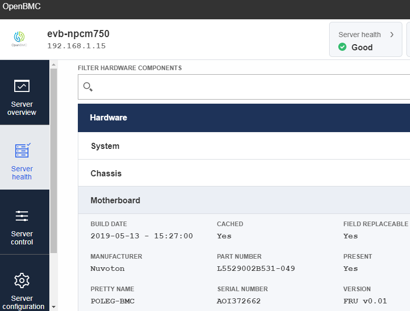
Field Replaceable Unit. The FRU Information is used to primarily to provide “inventory” information about the boards that the FRU Information Device is located on. In Poleg, we connect EEPROM component as FRU Information Device to support this feature. Typically, this feature is used by the BMC to "monitor" host server health about H/W copmonents status.
Source URL
This is a patch for enabling FRU feature in phosphor-impi-fru on Nuvoton's NPCM750. It's verified with Nuvoton's NPCM750 solution (which is referred as Poleg here) with Atmel 24c04 EEPROM copmonent.
-
How to use
-
Prepare a Poleg EVB with up-to-date boot block, Uboot and OpenBMC versions with this FRU patch applied. Check with Nuvoton support for the most recent versions.
-
Prepare a Atmel 24c04 EEPROM component, then connect SCL pin with pull up resistor 3.3V to pin 1 and SDA pin with pull up resistor 3.3V to pin 2 of J4 SMBus header on Poleg EVB. The other pins WP/A1/A2 connect to GND and pin A0 no connect.
Here, we connect Atmel 24c04 eeprom i2c device to i2c bus 3 in Poleg for verify FRU. Thus, if you connect to the other i2c bus then you need to remeber modify related DTS for this i2c device
For example about DTS nuvoton-npcm750-evb.dts:
i2c3: i2c@83000 {
#address-cells = <1>;
#size-cells = <0>;
bus-frequency = <100000>;
status = "okay";

eeprom@50 {
      compatible = "atmel,24c04";
      pagesize = <16>;
      reg = <0x50>;
  };
According DTS modification, you also need to remember modify your EEPROM file description content about SYSFS_PATH and FRUID. Below is example for our EEPROM file description motherboard:
SYSFS_PATH=/sys/bus/i2c/devices/3-0050/eeprom
FRUID=1
SYSFS_PATH is the path according your DTS setting and FRUID is arbitrary number but need to match Fruid in config.yaml file. Below is example for when Fruid set as 1:
1: #Fruid /system/chassis/motherboard: entityID: 7 entityInstance: 1 interfaces: xyz.openbmc_project.Inventory.Decorator.Asset: BuildDate: IPMIFruProperty: Mfg Date IPMIFruSection: Board PartNumber: IPMIFruProperty: Part Number IPMIFruSection: Board Manufacturer: IPMIFruProperty: Manufacturer IPMIFruSection: Board SerialNumber: IPMIFruProperty: Serial Number IPMIFruSection: Board xyz.openbmc_project.Inventory.Item: PrettyName: IPMIFruProperty: Name IPMIFruSection: Board xyz.openbmc_project.Inventory.Decorator.Revision: Version: IPMIFruProperty: FRU File ID IPMIFruSection: Board -
Server health
Select
Server health->Hardware statuson Web-UI will show FRU Board Info/Chassis Info/Product Info area.
-
Maintainer
- Tim Lee
The Serial over LAN (SoL) via IPMI redirects the output of the server’s serial port to a command/terminal window on your workstation.
The user uses the ipmi tool like ipmiutil to interact with SOL via IPMI. Here the ipmiutil is used as an example.
This is a patch for enabling SOL via IPMI using phosphor-net-ipmid on Nuvoton's NPCM750.
The patch integrates phosphor-net-ipmid into Nuvoton's NPCM750 solution for OpenBMC.
It's verified with Nuvoton's NPCM750 solution (which is referred as Poleg here) and Supermicro MBD-X9SCL-F-0.
Source URL
How to use
-
Please follow instructions from step-1 to step-7 in SOL How to use section to configure your workstation, NPCM750 solution and Supermicro MBD-X9SCL-F-0.
-
Download the ipmiutil according to the host OS in your workstation.
Here it's assumed that the host OS is Windows 7 and ipmiutil for Windows is downloaded and used accordingly.
-
Run SOL:
-
Extract or install the ipmiutil package to a folder in your workstation in advance.
-
Launch a command window and navigate to that folder.
-
Input the following command in the command window.
ipmiutil sol -N 192.168.0.2 -U root -P 0penBmc -J 3 -V 4 -a -
(Optional) If the area doesn't display the UEFI setting clearly, the user could press the Esc key once.
- It shows a prompt window named
Exit Without Saving, chooseNoand press enter key to refresh the area for showing UEFI setting entirely.
- It shows a prompt window named
-
(Optional) Configure the
Propertiesof the command window to see the entire output of SOL.Screen Buffer Size Width: 200
Screen Buffer Size Height: 400
Window Size Width: 100
Window Size Height: 40
-
-
End SOL session:
- Press the "`" key (using the shift key) and "." key at the same time in the command window.
- Input the following command in the command window.
ipmiutil sol -N 192.168.0.2 -U root -P 0penBmc -J 3 -V 4 -d
Maintainer
- Tyrone Ting
- Stanley Chu
BMC Message Bridging provides a mechanism for routing IPMI Messages between different media.
Please refer to IPMI Website for details about Message Bridging.
- KCS to IPMB
The command "Send Message" is used to routing IPMI messages from KCS to IPMB via System Interface.
Later, the response to the bridged request is received by the BMC and routed into the Receive Message Queue and it is retrieved using a Get Message command.
The patch integrates the kcsbridge, ipmid and ipmbbridge projects.
It's verified with Nuvoton's NPCM750 solution (which is referred as Poleg here) and Supermicro MBD-X9SCL-F-0.
Source URL
- https://github.com/Nuvoton-Israel/openbmc/tree/master/meta-evb/meta-evb-nuvoton/meta-evb-npcm750/recipes-phosphor/images
- https://github.com/Nuvoton-Israel/openbmc/tree/master/meta-evb/meta-evb-nuvoton/meta-evb-npcm750/recipes-phosphor/ipmi
- https://github.com/Nuvoton-Israel/openbmc/tree/master/meta-evb/meta-evb-nuvoton/meta-evb-npcm750/recipes-kernel/linux
How to use
-
The user is expected to know how to follow the instructions in the section Setting up your OpenBMC project in Nuvoton-Israel/openbmc to build and program an OpenBMC image into Poleg EVBs.
-
Prepare a PC (which is referred as a build machine here) for building and programming the OpenBMC image.
The user is also expected to have general knowledge of ACPI/UEFI and know how to update the DSDT table in linux and build/update a linux kernel/driver.
-
-
Prepare two Nuvoton Poleg EVBs. One is named Poleg EVB A and the other is Poleg EVB B.
-
Connect pin 3-4 of J4 on Poleg EVB A with corresponding pins of J4 on Poleg EVB B, one on one.
-
Connect pin 12 of J3 on Poleg EVB A with corresponding pin of J3 on Poleg EVB B, one on one.
-
The connection needs a 1k resistor and a 3.3v supply from Poleg EVB A.
The component name of 3.3v supply is P4.
-
-
Follow instructions from step-1, step-2, step-3 and step-5 in SOL How to use section to set up your workstation, Poleg EVB A and Supermicro MBD-X9SCL-F-0.
Follow instructions from step-1 and step-5 in SOL How to use section to set up Poleg EVB B.
-
Install Ubuntu 14.04 64bit on Supermicro MBD-X9SCL-F-0 for the verification and login as a normal user.
The user is required to own root privileges on Ubuntu.
-
Poleg EVB A is configured to have its own slave address 0x10. Poleg EVB B is configured to have its own slave address 0x58.
Poleg EVB A treats Poleg EVB B as its attached device on SMBUS/I2C bus and vice versa.
-
In the build machine, download Nuvoton-Israel/openbmc git repository.
-
The patches for Poleg EVB A has already applied to OpenBmc v2.6
-
In the build machine, rebuild the linux kernel for OpenBMC. As an example, enter the following command in a terminal window (build environment is configured in advance):
bitbake -C fetch virtual/kernel -
In the build machine, rebuild the OpenBmc image. As an example, enter the following command in a terminal window (build environment is configured in advance):
bitbake obmc-phosphor-image -
Follow the section Programming the images of Nuvoton-Israel/openbmc to program the updated image into Poleg EVB A.
-
-
Download patch to meet the requirement of step-5 for Poleg EVB B.
-
Download 0001-PATCH-change-i2c-addrees-for-Poleg-EVB-B.patch and apply patch by git command to configure Poleg EVB B's own slave address as 0x58 as follow.
git apply -v 0001-PATCH-change-i2c-addrees-for-Poleg-EVB-B.patch -
In the build machine, rebuild the linux kernel for OpenBMC. As an example, enter the following command in a terminal window (build environment is configured in advance):
bitbake -C fetch virtual/kernel -
In the build machine, rebuild the ipmbbridge for OpenBMC. As an example, enter the following command in a terminal window (build environment is configured in advance):
bitbake -C fetch phosphor-ipmi-ipmb -
In the build machine, rebuild the OpenBmc image. As an example, enter the following command in a terminal window (build environment is configured in advance):
bitbake obmc-phosphor-image -
Follow the section Programming the images of Nuvoton-Israel/openbmc to program the updated image into Poleg EVB B.
-
-
Modify the system interface driver in Ubuntu 14.04 on Supermicro MBD-X9SCL-F-0 to communicate with Poleg EVB A.
-
Download the kernel source code of Ubuntu 14.04 on Supermicro MBD-X9SCL-F-0 and locate the system interface driver source code.
-
Locate the code in the function init_ipmi_si of ipmi_si_intf.c.
enum ipmi_addr_src type = SI_INVALID; -
Add the code next to the sentence "enum ipmi_addr_src type = SI_INVALID".
return -1; -
Rebuild the system interface driver and replace ipmi_si.ko of Ubuntu 14.04 with the one just rebuilt on Supermicro MBD-X9SCL-F-0.
The original ipmi_si.ko is located at /lib/modules/`$(uname -r)`/kernel/drivvers/char/ipmi
-
Undo the "return -1" modification in the function init_ipmi_si of ipmi_si_intf.c.
- Rebuild the system interface driver again and leave the regenerated ipmi_si.ko in the kernel source code ipmi directory for system interface driver.
-
Reboot Ubuntu 14.04 on Supermicro MBD-X9SCL-F-0.
-
-
Update the DSDT table in Ubuntu 14.04 on Supermicro MBD-X9SCL-F-0.
-
Study the section How to build a custom DSDT into an initrd of overriding-dsdt and initrd_table_override.txt to override DSDT in the initrd image of Ubuntu 14.04 and rebuild the Ubuntu kernel on Supermicro MBD-X9SCL-F-0.
-
In the DSDT table, update the OEMRevision field in DefinitionBlock.
-
In the DSDT table, create two objects used for accessing Poleg EVB A KCS devices via 0x4E, 0x4F.
Name (IDTP, 0x0CA4) Name (ICDP, 0x0CA5) -
Locate the code section like below.
Device (SPMI) { ... Name (_STR, Unicode ("IPMI_KCS")) Name (_UID, Zero) -
Add the codes below following the sentence "Name (_UID, Zero)".
OperationRegion (IPST, SystemIO, ICDP, One) Field (IPST, ByteAcc, NoLock, Preserve) { STAS, 8 } -
Locate the code section like below in the same SPMI code section just mentioned.
Method (_STA, 0, NotSerialized) ... If (LEqual (Local0, 0xFF)) { ... -
Add the codes below inside the "If" sentence scope.
Store (0x11, LDN) Store (0x1, ACTR) Store (0x0C, IOAH) Store (0xA4, IOAL) Store (0x0C, IOH2) Store (0xA5, IOL2) -
Rebuild the modified DSDT table and regenerate the initrd image of Ubuntu 14.04 on Supermicro MBD-X9SCL-F-0.
-
Reboot Supermicro MBD-X9SCL-F-0 to load the overriden DSDT.
-
-
(Optional)Create shell scripts in Ubuntu 14.04 on Supermicro MBD-X9SCL-F-0.
-
The scripts here are just for convenience and for reference.
-
Download and build ioport-1.2.tar.gz.
- Locate the generated outb executive.
-
Create a script named "kcs_switch.sh" for example to configure the access to the kcs device of Poleg EVB A from Supermicro MBD-X9SCL-F-0.
-
The user needs to modify the path to the outb executive in the script (kcs_switch.sh) below.
#!/bin/sh outb 0x4e 0x07 outb 0x4f 0x11 outb 0x4e 0x30 outb 0x4f 0x1 outb 0x4e 0x60 outb 0x4f 0x0C outb 0x4e 0x61 outb 0x4f 0xA4 outb 0x4e 0x62 outb 0x4f 0x0C outb 0x4e 0x63 outb 0x4f 0xA5 -
Create a script name "insert_ipmi_mod.sh" for example to use the regenerated KCS driver in the kernel source code ipmi directory metioned in step-8.
-
The user needs to modify the path to the KCS driver in insert_ipmi_mod.sh below.
#!/bin/sh sudo insmod ./ipmi_devintf.ko sudo insmod ./ipmi_si.ko -
Make sure that two scripts above are executable.
-
-
Install the ipmiutil in Ubuntu 14.04 on Supermicro MBD-X9SCL-F-0.
- Download, extract, build and install ipmiutil-3.1.2.tar.gz.
- Open a terminal window and navigate to the extracted folder of ipmiutil-3.1.2.tar.gz.
- Input the following command in the terminal window.
sudo ./scripts/ipmi_if.sh - This generates /var/lib/ipmiutil/ipmi_if.txt.
- Edit /var/lib/ipmiutil/ipmi_if.txt with the root privilege.
- The value for "Base Address:" is 0x0000000000000CA2 (I/O) and modify it to 0x0000000000000CA4 (I/O).
-
Test message bridging.
-
Power up or reboot Poleg EVB A and Poleg EVB B. Make sure that login screens of Poleg EVBs are displayed on the terminal window (e.g. Tera Term) on your workstation.
-
Power up or reboot Supermicro MBD-X9SCL-F-0 and log in Ubuntu 14.04 as a normal user.
-
Open a terminal window and execute kcs_switch.sh and insert_ipmi_mod.sh created in step-10 with the root privilege.
-
If the scripts are not created, input the contents of kcs_switch.sh and insert_ipmi_mod.sh except the #!/bin/sh line manually.
-
The user can use the following command in a terminal window under Ubuntu 14.04 on Supermicro MBD-X9SCL-F-0 to verify Poleg system interface.
dmesg | grep -i "bmc" -
The user can check the man_id. For example, the man_id is 0x000000 for this case.
-
-
Enter the following command in a terminal window as a normal user of Ubuntu 14.04 on Supermicro MBD-X9SCL-F-0.
sudo ipmiutil cmd 18 34 02 10 18 d8 20 0e 01 d1 -x -s -j -F kcsThe example command in the data field of "Send Message" command is "Get Device ID".
-
Enter the following command in a terminal window as a normal user of Ubuntu 14.04 on Supermicro MBD-X9SCL-F-0.
sudo ipmiutil cmd 18 33 -x -s -j -F kcsThe response to "Get Device ID" command might be "respData[len=26]: 1c 33 00 02 1e c2 58 00 01 00 00 00 02 03 02 00 00 00 00 00 00 00 00 00 00 a0".
-
Maintainer
- Stanley Chu
- Tyrone Ting

The Lightweight Directory Access Protocol (LDAP) is an open, vendor-neutral, industry standard application protocol for accessing and maintaining distributed directory information services over an Internet Protocol (IP) network.
LDAP is specified in a series of Internet Engineering Task Force (IETF) Standard Track publications called Request for Comments (RFCs), using the description language ASN.1.
A common use of LDAP is to provide a central place to store usernames and passwords. This allows many different applications and services to connect to the LDAP server to validate users.
Source URL
- https://github.com/Nuvoton-Israel/openbmc/tree/master/meta-evb/meta-evb-nuvoton/meta-evb-npcm750/dlc/ldap-support-user-management
- https://github.com/Nuvoton-Israel/openbmc-util/tree/master/ldap_server
How to use
-
The user is expected to know how to follow the instructions in the section Setting up your OpenBMC project in Nuvoton-Israel/openbmc to build and program an OpenBMC image into Poleg EVBs.
Prepare a PC which builds OpenBMC. (called the build machine hereafter)
The user is also expected to have knowledge of LDAP and its operations. -
Install Ubuntu 16.04 64 bit (called Ubuntu hereafter) on a PC which is used as a LDAP server and log in it with an account with root privilege.
-
Set up the LDAP server and its configurations in Ubuntu.
-
Open a terminal and input the following commands to install required software packages in advance.
sudo apt-get install git sudo apt-get install libsasl2-dev sudo apt-get install g++ wget http://download.oracle.com/berkeley-db/db-4.8.30.zip unzip db-4.8.30.zip cd db-4.8.30 cd build_unix/ ../dist/configure --prefix=/usr/local --enable-cxxmake sudo make install -
Install OpenSSL
- Download openssl-1.0.2j.tar.gz.
- Extract openssl-1.0.2j.tar.gz.
- Open a terminal, navigate to the extracted folder and input the following commands to install OpenSSL.
./config shared --prefix=/usr/local
make
make test
sudo make install
-
Install OpenLDAP
-
Download OpenLDAP from https://github.com/openldap/openldap
-
Open a terminal and input the following command to build and install OpenLDAP.
./configure CPPFLAGS="-I/usr/local/include -I/usr/local/include/openssl" LDFLAGS="-L/usr/local/lib -Wl,-rpath,/usr/local/lib" --prefix=/usr/local --enable-syncprov=yes --enable-crypt=yes --enable-accesslog=yes --enable-auditlog=yes --enable-constraint=yes --enable-ppolicy=yes --enable-modules --enable-mdb --enable-spasswd --enable-debug=yes --enable-syslog --enable-slapd --enable-cleartext --enable-monitor --enable-overlays -with-threads --enable-rewrite --enable-syncprov=yes --with-tls=opensslThe description above is one line only.
make depend
make
sudo make install
-
-
Execute LDAP server
-
Open a terminal and input the following command.
sudo /usr/local/libexec/slapd -d 1 -h 'ldaps:/// ldap:/// ldapi:///'To stop LDAP server execution, press Ctrl key and C key at the same time in the terminal.
Now please stop the LDAP server execution.
-
-
Generate security configurations for the LDAP server running in Ubuntu.
Here a two-stage signing process is applied.
You could also use the self-signed CA and cert for the configuration if your company uses them.-
Generate the CA key and cert. Open a terminal and input the following commands.
openssl ecparam -genkey -name prime256v1 -out ca_server.key
openssl req -x509 -new -key ca_server.key -days 3650 -out ca_server.pem -subj '/C=OO/ST=OO/L=OO/O= OO/OU= OO /CN= OO'
Define these OO for the arguments C, ST, etc. according to your configurations.
Please refer to the following link for explanations of the arguments C, ST, etc.
https://www.shellhacks.com/create-csr-openssl-without-prompt-non-interactive/. -
Generate the LDAP key and CSR. In the same terminal, input the following commands.
openssl ecparam -genkey -name prime256v1 -out ldap_server.key
openssl req -new -key ldap_server.key -out ldap_server.csr -subj '/C=OO /ST=OO /L=OO/O=OO/OU=OO/CN=ldap.example.com'
Define these OO for the arguments C, ST, etc. according to your configurations.
Note that the field CN in ldap_server.csr must be set to the fully qualified domain name of the LDAP server. -
Generate ldap cert signed with CA cert. In the same terminal, input the following command.
openssl x509 -req -days 365 -CA ca_server.pem -CAkey ca_server.key -CAcreateserial -CAserial serial -in ldap_server.csr -out ldap_server.pem
-
-
Store and specify locations of keys and certs.
-
Edit /usr/local/etc/openldap/slapd.conf in Ubuntu with root privilege to update fields as examples shown below.
TLSCACertificateFile /etc/ldap/ca_certs.pem
TLSCertificateFile /etc/ssl/certs/ldap_server.pem
TLSCertificateKeyFile /etc/ssl/private/ldap_server.key
TLSCACertificatePath /etc/ldap -
Copy ca_certs.pem, ldap_server.pem and ldap_server.key into locations specified above with root privilege.
-
-
Add LDAP schema and LDIF.
-
Download user_exp.schema and save it at /usr/local/etc/openldap/schema with root privilege in Ubuntu.
-
Modify /usr/local/etc/openldap/slapd.conf in Ubuntu with root privilege to specify the schema just saved.
include /usr/local/etc/openldap/schema/user_exp.schema
-
Download bdn.ldif, ap_group.ldif, bmc.ldif, group.ldif, people.ldif and privRole.ldif to a temporary folder in Ubuntu.
-
Open a terminal, navigate to the temporary folder for storing LDIF and input the following commands to add these LDIF into the LDAD server in Ubuntu.
sudo slapadd -l ./bdn.ldif
sudo slapadd -l ./ap_group.ldif
sudo slapadd -l ./bmc.ldif
sudo slapadd -l ./group.ldif
sudo slapadd -l ./people.ldif
sudo slapadd -l ./privRole.ldif
-
-
Execute LDAP server.
- Open a terminal and input the following command in the terminal.
sudo /usr/local/libexec/slapd -d 1 -h 'ldaps:/// ldap:/// ldapi:///'
-
-
Setup LDAP client configuration on Poleg.
-
Open a terminal in the build machine and navigate to the directory which contains OpenBMC source codes. The directory is called OPENBMCDIR hereafter.
- Copy all directories and their containing files from https://github.com/Nuvoton-Israel/openbmc/tree/master/meta-evb/meta-evb-nuvoton/meta-evb-npcm750/dlc/ldap-support-user-management under OPENBMCDIR/meta-evb/meta-evb-nuvoton/meta-evb-npcm750 directory according to their default hierarchy.
-
Update OPENBMCDIR/meta-evb/meta-evb-nuvoton/meta-evb-npcm750/recipes-phosphor/nss-pam-ldapd/files/nslcd.conf. (optional)
-
The IP address for the LDAP server in Ubuntu is configured as 192.168.0.101. Modify the field uri ldap in nslcd.conf according to your network configuration.
uri ldap://192.168.0.101/
-
The modification above is done in OpenBmc build time. If you would like to modify uri in OpenBmc run time, follow the instructions below after logging into Poleg in the console program (like Tera Term) with the root account (root/0penBmc).
The console program is used to display a debug console provided by Poleg.
vi /etc/nslcd.confLocate the line uri ldap://192.168.0.101/. Modify the field uri ldap according to your network configuration.
systemctl stop nslcd
systemctl start nslcd
-
-
In the build machine, open a terminal window (build environment is configured in advance and the working directory is at OPENBMCDIR/build) to input the following commands to build the OpenBMC image.
bitbake -C fetch libpam bitbake -C fetch pamela bitbake -C fetch nss-pam-ldapd bitbake -C fetch dropbear bitbake -C fetch phosphor-rest bitbake -C fetch phosphor-webui bitbake obmc-phosphor-image -
Follow the section Programming the images of Nuvoton-Israel/openbmc to program the updated image into Poleg.
-
-
Test LDAP server.
-
Connect Poleg(J12 header) to the PC running Ubuntu with an ethernet cable and power on Poleg.
-
Log in Poleg from the console program (like Tera Term) with the root account (root/0penBmc).
The console program is used to display a debug console provided by Poleg.
-
Set up IP addresses for Poleg and Ubuntu so that they can ping each other.
-
For example, set Poleg's IP address to 192.168.0.2. Input the following command in the console program.
ifconfig eth2 192.168.0.2Please replace 192.168.0.2 with your IP configuration for Poleg.
-
-
Execute the following command in the console program.
ldapsearch -ZZ -h 192.168.0.101 -D "cn=admin,dc=ldap,dc=example,dc=com" -b "dc=ldap,dc=example,dc=com" -w secretPlease replace 192.168.0.101 with your IP configuration for Ubuntu.
The ldapsearch example is to display all the data stored in the LDAP server using a TLS connection. -
You could use the account user1 stored in the LDAP server to log in WebUI running on Poleg.


-
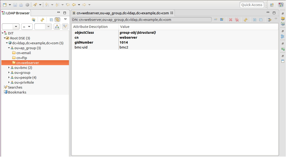
Some descriptions about the LDIF used by the LDAP server and authentication process are provided here. Please refer to the six snapshots just above.
To login using an account, the authentication logic has to check the following criteria.
bmc-uid: It stands for the BMC machine that the account is used to login. The BMC machines are grouped by DN ou=ap_group,dc=ldap,dc=example,dc=com. One BMC machine can be in multiple groups at the same time. (see ap_group below)
ap_group: Applications like web server, email, ftp and so on are deployed on the servers attched by BMC machines. Therefore, grouping by applications is taken into the authentication process. The authentication refuses an account to log in some BMC machine if that machine is not deployed under the certain ap_group the account also joins.
people: It contains the account information (login/privileges) stored in the LDAP server. An account can join multiple ap_group simutaneously.
user-login-disabled: While this attribute's value is 1, it is not allowed to login with the account's membership of the specific ap_group.
user-login-interface: It's used as a channel via that the account logins for an ap_group. For example, web stands for logging in a BMC machine via WebUI. If web does not exist in any user-login-interface attributes an account owns under a certain ap_group, it means that the user cannot use this account to login as a member of the preferred ap_group via WebUI. -
Use an LDAP tool to modify the field macAddress of the DN bmc-uid=bmc1,ou=bmc,dc=ldap,dc=example,dc=com stored in the LDAP server.
The modification is to use the mac address of the ethernet module on the Poleg EVB you currently test with.
-
To get the mac address desired, input the following command in the console program.
ifconfig eth0Locate the keyword HWaddr displayed in the console program.
Copy the value next to HWaddr to override the value of the field macAddress of the DN bmc-uid=bmc1,ou=bmc,dc=ldap,dc=example,dc=com. -
Launch a browser and navigate to the Poleg's IP address.
Bypass the secure warning and continue to the website.
-
Use user1/123 to log in WebUI.
user1 is the login ID.
123 is the login password.
The bmc-uid for the BMC machine used for this test is bmc1. According to the LDIF provided, the BMC machine bmc1 is deployed under the ap_group email and the the BMC machine bmc2 is deployed under ap_group webserver. Also one can tell from the snapshots, user1 and user2 have different user-login-interface settings for the ap_group email and ap_group webserver respectively.
User1 is able to log on bmc1 via WebUI since the following conditions are met: the BMC machine bmc1 is deployed under ap_group email.; user1 is a member of the ap_group email.; user1 has an user-login-interface setting as web for that group and value of user1's user-login-disabled attribute is not set.
Although user2 is also a member of the ap_group email, it does not have an user-login-interface setting as web for that group. Under such conditions, user2 is not allowed to log on bmc1. User2 does have an user-login-interface setting as web for the ap_group webserver but bmc1 is not deployed under the ap_group webserver.
The description above explains why user1 is used for this test.
-
Password modification is also available to LDAP accounts via WebUI.
-
Log in WebUI using user1/123 as mentioned in previous phrase.
-
Navigate to
Usersmenu item on the left panel and select it. -
A sub menu item
Manage user accountpops up and select it. -
Input the current password value for user1.
The password is set to 123 by default.
The input location is right below CURRENT PASSWORD text area. -
Input a new password twice.
The input locations are right below NEW PASSWORD and RETYPE NEW PASSWORD text area.
-
Press the
Save changebutton.A message Success! User Password has been changed! is expected to show then.
-
Log out WebUI and login again with the new password for user1.
-
-
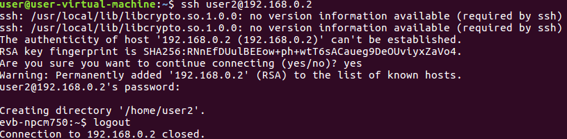
Log in Poleg via SSH using an LDAP account.
-
Make sure that configurations stated in Step 5 for Poleg and Ubuntu are set accordingly and ping between Ubuntu and Poleg is okay.
-
Install ssh in Ubuntu with root privilege if ssh client is not available. Open a terminal and input the following command.
sudo apt-get install ssh -
Open a terminal in Ubuntu to log in Poleg using the LDAP account user1 and its password via SSH. Input the following command in the terminal.
Please replace 192.168.0.2 with your IP configuration for Poleg.
-
-
Maintainer
- Tyrone Ting
JTAG master is implemented on BMC to debug host CPU or program CPLD / FPGA device.

How to use
- Prepare a Poleg EVB and a target board (in our test, we use NUC950).
- Connect pins of Jtag on NUC950 to Poleg EVB:
- Connect Jtag TCK pin to pin2 of J11 on Poleg EVB.
- Connect Jtag TDI pin to pin7 of J11 on Poleg EVB.
- Connect Jtag TDO pin to pin8 of J11 on Poleg EVB.
- Connect Jtag TMS pin to pin10 of J11 on Poleg EVB.
- Prepare Jtag driver module and Jtag socket svc deamon:
- Jtag driver
- make sure the kernel config is enabled:
CONFIG_NUVOTON_JTAG=y
- make sure the kernel config is enabled:
- Jtag socket svc daemon:
- In the build machine, build daemon by:
bitbake jtag-socket-svc - Copy generated daemon "jtag_socket_svc" to Poleg EVB. "jtag_socket_svc" should be loacted at <openbmc folder>/build/tmp/work/armv7a-openbmc-linux-gnueabi/jtag-socket-svc/<version>/image/usr/bin/
- In the build machine, build daemon by:
- Jtag driver
- Prepare a guest PC and jtag client tool which will send At scale debug commands to daemon "jtag_socket_svc" on Poleg EVB via ethernet.
- Here is an example jtag client tool for NUC950 (target board)
- Download the example tool from https://github.com/Nuvoton-Israel/openbmc-util/tree/master/jtag_socket_client_arm
- Make sure that python3 is installed on the guest PC.
- Here is an example jtag client tool for NUC950 (target board)
- Configure the ethernet communication between Poelg EVB and a guest PC:
- Connect an ethernet cable between your workstation and J12 header of Poleg EVB.
- Configure guest PC' ip address to 192.168.2.101 and the netmask to 255.255.255.0 as an example here.
- Configure Poleg EVB ip address to 192.168.2.100 and the netmask to 255.255.255.0. For example, input the following command in the terminal connected to Poleg EVB on your workstation and press enter key.
ifconfig eth2 192.168.2.100 netmask 255.255.255.0
- Run Jtag socket svc daemon:
- Run daemon "jtag_socket_svc" by inputing the following command in the terminal connected to Poleg EVB:
./jtag_socket_svc - Make sure the NUC950(target board) is powered on and Jtag connection is ready.
- Control NUC950(target board) via Jtag by jtag client tool on guest PC:
- Launch client jtag tool
python jtag_client.py - List commands the jtag client tool supports:
jtag_client>>>? - Halt the target board:
jtag_client>>>halt - Restore the target board:
jtag_client>>>go
- Launch client jtag tool
- Run daemon "jtag_socket_svc" by inputing the following command in the terminal connected to Poleg EVB:
The motherboard on server might have CPLD or FPGA components that require downloading firmware to these devices whenever server is powered on. BMC can help on this to program CPLD/FPGA via JTAG.
How to use
- Connect Poleg EVB to CPLD/FPGA device by JTAG interface.
- Build Programming Tool
bitbake loadsvf - Copy loadsvf executable binary from build/tmp/work/armv7a-openbmc-linux-gnueabi/loadsvf/<version>/image/usr/bin/ to Poleg EVB.
- Put CPLD/FPGA image in USB disk and mount the USB disk on Poleg EVB
- run loadsvf on Poleg to program CPLD/FPGA
For more usages of loadsvf, please check here
loadsvf -s ${usb_mount_point}/fpga.svf -d /dev/jtag_drv
Maintainer
- Stanley Chu
- User management
- Improve IPMI
- Improve sensor/event framework
- Host firmware update
- Redfish
- Boot control
| Command | KCS | RMCP+ | IPMB |
|---|---|---|---|
| IPM Device Global Commands | |||
| Device ID | V | V | V |
| Cold Reset | V | V | V |
| Warm Reset | V | V | V |
| Get Self Test Results | V | V | V |
| Manufacturing Test On | - | - | - |
| Set ACPI Power State | V | V | V |
| Get ACPI Power State | V | V | V |
| Get Device GUID | V | V | V |
| Get NetFn Support | - | - | - |
| Get Command Support | - | - | - |
| Get Command Sub-function Support | - | - | - |
| Get Configurable Commands | - | - | - |
| Get Configurable Command Sub-functions | - | - | - |
| Set Command Enables | - | - | - |
| Get Command Enables | - | - | - |
| Set Command Sub-function Enables | - | - | - |
| Get Command Sub-function Enables | - | - | - |
| Get OEM NetFn IANA Support | - | - | - |
| BMC Watchdog Timer Commands | |||
| Reset Watchdog Timer | V | V | V |
| Set Watchdog Timer | V | V | V |
| Get Watchdog Timer | V | V | V |
| BMC Device and Messaging Commands | |||
| Set BMC Global Enables | V | V | V |
| Get BMC Global Enables | V | V | V |
| Clear Message Flags | - | - | - |
| Get Message Flags | V | V | V |
| Enable Message Channel Receive | - | - | - |
| Get Message | V | - | - |
| Send Message | V | - | - |
| Read Event Message Buffer | V | V | V |
| Get System GUID | V | V | V |
| Set System Info Parameters | V | V | V |
| Get System Info Parameters | V | V | V |
| Get Channel Authentication Capabilities | V | V | V |
| Get Session Challenge | - | - | - |
| Activate Session | - | - | - |
| Set Session Privilege Level | V | V | V |
| Close Session | V | V | V |
| Get Session Info | - | - | - |
| Get AuthCode | - | - | - |
| Set Channel Access | V | V | V |
| Get Channel Access | V | V | V |
| Get Channel Info Command | V | V | V |
| User Access Command | V | V | V |
| Get User Access Command | V | V | V |
| Set User Name | V | V | V |
| Get User Name Command | V | V | V |
| Set User Password Command | V | V | V |
| Activate Payload | - | V | - |
| Deactivate Payload | - | V | - |
| Get Payload Activation Status | - | V | - |
| Get Payload Instance Info | - | V | - |
| Set User Payload Access | - | - | - |
| Get User Payload Access | - | - | - |
| Get Channel Payload Support | - | - | - |
| Get Channel Payload Version | - | - | - |
| Get Channel OEM Payload Info | - | - | - |
| Master Write-Read | - | - | - |
| Get Channel Cipher Suites | V | V | V |
| Suspend/Resume Payload Encryption | - | - | - |
| Set Channel Security Keys | - | - | - |
| Get System Interface Capabilities | - | - | - |
| Firmware Firewall Configuration | - | - | - |
| Chassis Device Commands | |||
| Get Chassis Capabilities | V | V | V |
| Get Chassis Status | V | V | V |
| Chassis Control | V | V | V |
| Chassis Reset | V | V | V |
| Chassis Identify | V | V | V |
| Set Front Panel Button Enables | - | - | - |
| Set Chassis Capabilities | V | V | V |
| Set Power Restore Policy | V | V | V |
| Set Power Cycle Interval | V | V | V |
| Get System Restart Cause | - | - | - |
| Set System Boot Options | V | V | V |
| Get System Boot Options | V | V | V |
| Get POH Counter | V | V | V |
| Event Commands | |||
| Set Event Receiver | - | - | - |
| Get Event Receiver | - | - | - |
| Platform Event | - | - | - |
| PEF and Alerting Commands | |||
| Get PEF Capabilities | - | - | - |
| Arm PEF Postpone Timer | - | - | - |
| Set PEF Configuration Parameters | - | - | - |
| Get PEF Configuration Parameters | - | - | - |
| Set Last Processed Event ID | - | - | - |
| Get Last Processed Event ID | - | - | - |
| Alert Immediate | - | - | - |
| PET Acknowledge | - | - | - |
| Sensor Device Commands | |||
| Get Device SDR Info | V | V | V |
| Get Device SDR | V | V | V |
| Reserve Device SDR Repository | V | V | V |
| Get Sensor Reading Factors | - | - | - |
| Set Sensor Hysteresis | - | - | - |
| Get Sensor Hysteresis | - | - | - |
| Set Sensor Threshold | - | - | - |
| Get Sensor Threshold | V | V | V |
| Set Sensor Event Enable | - | - | - |
| Get Sensor Event Enable | - | - | - |
| Re-arm Sensor Events | - | - | - |
| Get Sensor Event Status | - | - | - |
| Get Sensor Reading | V | V | V |
| Set Sensor Type | - | - | - |
| Get Sensor Type | V | V | V |
| Set Sensor Reading And Event Status | V | V | V |
| FRU Device Commands | |||
| Get FRU Inventory Area Info | V | V | V |
| Read FRU Data | V | V | V |
| Write FRU Data | V | V | V |
| SDR Device Commands | |||
| Get SDR Repository Info | V | V | V |
| Get SDR Repository Allocation Info | - | - | - |
| Reserve SDR Repository | V | V | V |
| Get SDR | V | V | V |
| Add SDR | V | V | V |
| Partial Add SDR | - | - | - |
| Delete SDR | - | - | - |
| Clear SDR Repository | - | - | - |
| Get SDR Repository Time | - | - | - |
| Set SDR Repository Time | - | - | - |
| Enter SDR Repository Update Mode | - | - | - |
| Exit SDR Repository Update Mode | - | - | - |
| Run Initialization Agent | - | - | - |
| SEL Device Commands | |||
| Get SEL Info | V | V | V |
| Get SEL Allocation Info | V | V | V |
| Reserve SEL | V | V | V |
| Get SEL Entry | V | V | V |
| Add SEL Entry | V | V | V |
| Partial Add SEL Entry | - | - | - |
| Delete SEL Entry | V | V | V |
| Clear SEL | V | V | V |
| Get SEL Time | V | V | V |
| Set SEL Time | V | V | V |
| Get Auxiliary Log Status | - | - | - |
| Set Auxiliary Log Status | - | - | - |
| Get SEL Time UTC Offset | - | - | - |
| Set SEL Time UTC Offset | - | - | - |
| LAN Device Commands | |||
| Set LAN Configuration Parameters | V | V | V |
| Get LAN Configuration Parameters | V | V | V |
| Suspend BMC ARPs | - | - | - |
| Get IP/UDP/RMCP Statistics | - | - | - |
| Serial/Modem Device Commands | |||
| Set Serial/Modem Mux | - | - | - |
| Set Serial Routing Mux | - | - | - |
| SOL Activating | - | V | - |
| Set SOL Configuration Parameters | - | V | - |
| Get SOL Configuration Parameters | - | V | - |
| Command Forwarding Commands | |||
| Forwarded Command | - | - | - |
| Set Forwarded Commands | - | - | - |
| Get Forwarded Commands | - | - | - |
| Enable Forwarded Commands | - | - | - |
V: Verified
-: Unsupported
| Type | Size | Note |
|---|---|---|
| image-uboot | 415 KB | u-boot 2019.01 + bootblock for Poleg only |
| image-kernel | 4.4 MB | linux 4.19.16 version |
| image-rofs | 19.2 MB | bottom layer of the overlayfs, read only |
| image-rwfs | 0 MB | middle layer of the overlayfs, rw files in this partition will be created at runtime, with a maximum capacity of 2MB |
- 2018.07.23 First release Remote-KVM
- 2018.08.02 First release SOL
- 2018.08.07 Modify Readme.md for adding description about SOL How to use
- 2018.09.07 Update SOL for WebUI and IPMI
- 2018.09.10 Update System/Time/SNTP
- 2018.09.12 Update IPMI Comamnds Verified Table
- 2018.09.13 Update Time settings of System/Time
- 2018.09.13 Update obmc-ikvm part for WebUI
- 2018.09.14 First release VM
- 2018.09.14 Update IPMI Commands Verified Table
- 2018.09.21 Add NTP screen snapshot for System/Time/SNTP
- 2018.10.05 Update webui and patch of webui and interface and vm-own.png
- 2018.10.11 Add Sensor
- 2018.11.16 Add obmc-ikvm support in bmcweb
- 2018.11.22 Enable firmware update support
- 2018.11.23 Update Sensor description about FAN How to use
- 2018.11.29 Update Server power operations of Server control about How to use
- 2018.12.27 Add Chassis Buttons about How to use
- 2019.01.02 Add LDAP server setup and test
- 2019.03.13 Modify Server power operation of Server control about How to use
- 2019.03.19 Update IPMI Comamnds Verified Table
- 2019.04.08 Update Kernel version to 4.19.16
- 2019.04.30 Add BIOS POST Code
- 2019.05.05 Update u-boot to 2019.01
- 2019.05.15 Add ADC config file
- 2019.05.23 Add FRU for Server health